


Robotguy
Member
- Joined
- Jun 30, 2010
- Messages
- 12
- Reaction score
- 0
Even though I'm new, I thought it might be useful to post the build of my "custom" electric engine (and by "custom" I mean that I'm making it up as I go.) I thought it might be useful as a place to point beginners "Don't do it like this one!"
The idea for this engine is a flywheel and crankshaft with a "piston" made from a magnet. When the piston is in the correct position a burst of current will pulse through the coil and drive the flywheel.
As I posted in my introduction post, I don't have very much experience at all, but I have spent over 10 hours looking over all of the wonderful projects on the forum. As a result I decided to finally, after over 2 years, tram my mill. I had been avoiding it because I didn't have any idea how to do it using the dial indicator that I had. So today was spent building a "tool" to mount my dial indicator in the spindle. I used a 3/8" bolt with the head cut off and a bit of scrap aluminum square tube.
(Click the image for a bigger version)
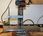
Lo and behold it was off about .015" from side to side and about .010" from front to back. I fiddled with the bolts that hold the column and placed a .010" brass shim in the right side, and a .005" brass shim in the front. That seemed to level things out a bit.
Next I retired to the living room to draw out the flywheel (using a 12 year old version of AutoCAD) and produce some G-code (with ACE converter).

The white is the finished part, the red is the toolpath, and the green is the finish toolpath (should take off the last .005"). I have some .5" brass I picked up from the local surplus metal distributor, but I think I'll test the design on some .250" aluminum.
OK. Time to go try the program.
The idea for this engine is a flywheel and crankshaft with a "piston" made from a magnet. When the piston is in the correct position a burst of current will pulse through the coil and drive the flywheel.
As I posted in my introduction post, I don't have very much experience at all, but I have spent over 10 hours looking over all of the wonderful projects on the forum. As a result I decided to finally, after over 2 years, tram my mill. I had been avoiding it because I didn't have any idea how to do it using the dial indicator that I had. So today was spent building a "tool" to mount my dial indicator in the spindle. I used a 3/8" bolt with the head cut off and a bit of scrap aluminum square tube.
(Click the image for a bigger version)

Lo and behold it was off about .015" from side to side and about .010" from front to back. I fiddled with the bolts that hold the column and placed a .010" brass shim in the right side, and a .005" brass shim in the front. That seemed to level things out a bit.
Next I retired to the living room to draw out the flywheel (using a 12 year old version of AutoCAD) and produce some G-code (with ACE converter).
The white is the finished part, the red is the toolpath, and the green is the finish toolpath (should take off the last .005"). I have some .5" brass I picked up from the local surplus metal distributor, but I think I'll test the design on some .250" aluminum.
OK. Time to go try the program.


")


