


jagwinn
Active Member
I went to the site in the signature of fellow metalist, Cedge of South Carolina, and saw the curved cylinder engine in his collection. Here is information on this engineering concept from the 1800. In fact it is the machine tool used to bore such a device.
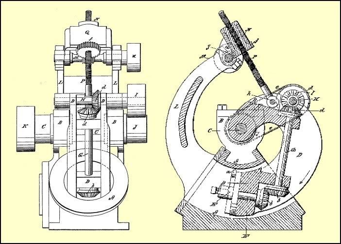
This machine was patented in 1864 by William Wright and was described as an "improved machine for boring curved cylinders for steam engines and other purposes", so obviously other principles had been used previously.
The operation is such that the cylinder A, to be bored, has either lugs cast & bored concentric to the arc of the cylinder or suitable lugs B, are fastened to the cylinder to allow the main shaft Cabout which the arm Dpivots to be fitted. If such independent lugs are used, the upright L could be made as to mount off them.
As can been seen above, the cutter a is drven by the gearing via the bevel gears and the pulleys I & J, power being applied to mainshaft pulley K.
The feed is operated by the nut N, rotated by the worm shaft M which is powered via a belt (not shown) from pulley J, acting on the threaed rod p, to cause the arm D to rotate about C.
--------------------------------------------------------------------------------
The above machine may may have been the type that the Woodruff & Beach Iron Works of Hartford Connecticut used when they built the engines of the USS Pequot.
A contemporary description of the engines was:
"The engines of the Pequot were built here, on a new plan. The cylinders are curved tubes; segments of a circle, thirty inches diameter. The piston rod is a complete circle, corresponding to the radius of the tube and works on centers. The connecting rod leads to the piston rod without the intervention of a cross head. These engines are reputed to work well."
The Pequot was a Kansas Class Screw Gunboat, built at the Boston Naval Shipyard and commissioned on January 15 1864.