Colin Binnie's 'La Belles' for home construction.

Home Model Engine Machinist Forum

Help Support Home Model Engine Machinist Forum:

This site may earn a commission from merchant affiliate links, including eBay, Amazon, and others.

Tony Bird

Senior Member
Joined
Feb 20, 2011
Messages
822
Reaction score
895
Location
Cardiff, South Wales, UK
Hi

In May 2005 Colin Binnie started a thread in an egroup entitled;

‘La Belles’ for home construction.

Which started;

A long while ago in a galaxy far, far away…….

Well, about two months ago at Withington actually. I was watching a small loco belonging to Alan King circulating most charmingly with a train of tippers. And it looked right.


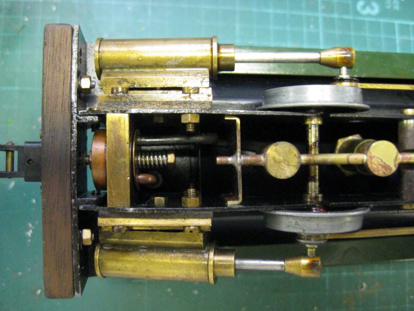
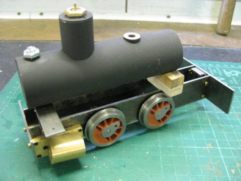
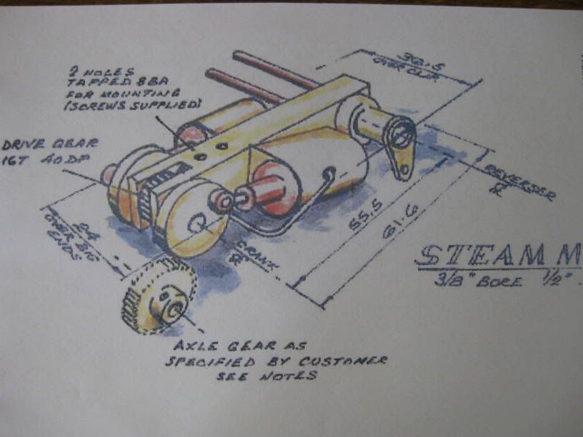
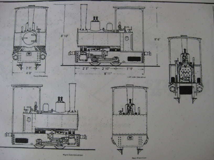
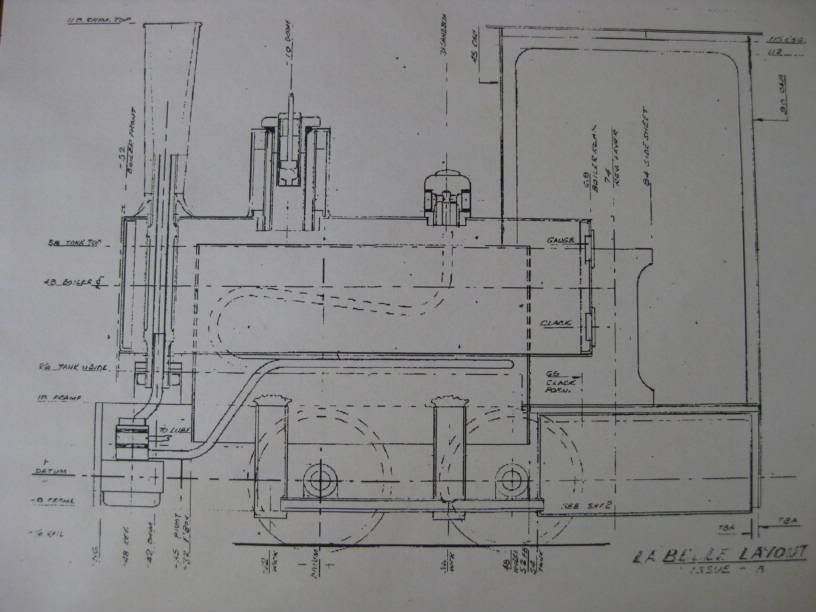
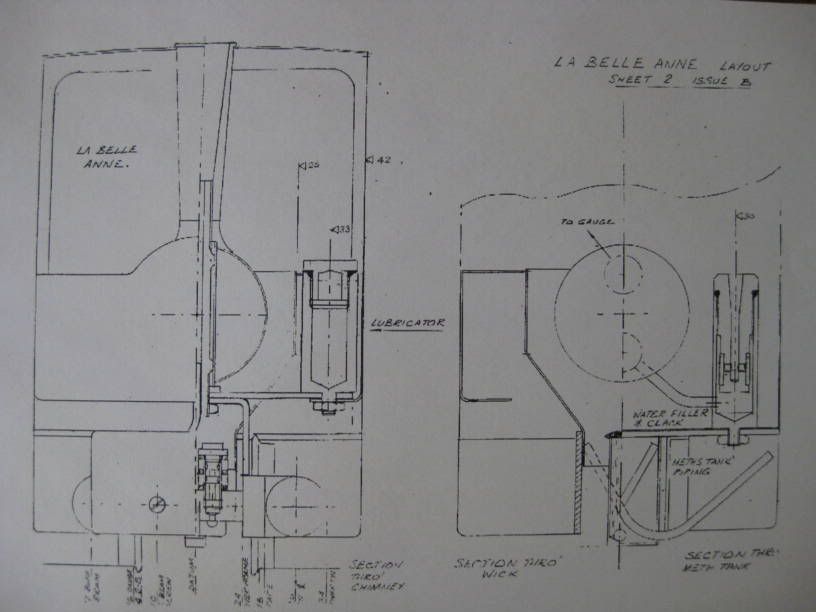
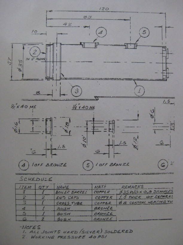
The email goes on to describe a locomotive that he is designing. It was to be a simple small locomotive suitable for a beginner to tackle. The design was for a 0-4-0 based on an early Decauville 5-ton locomotive. It was to have a meths fired ‘pot’ boiler with filler valve, to be powered by twin double acting oscillating cylinders, have lever reverse and a lubricator.

There were to be three versions;
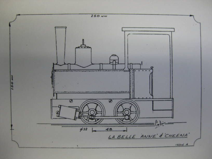
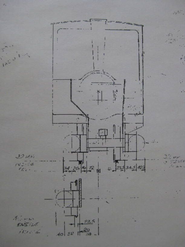
‘A’ 32mm gauge with inside frames known as ‘La Belle Anne’
‘B’ 32mm gauge with outside frames known as ‘La Belle Barbara’.
‘C’ 45mm gauge with inside frames known as ‘La Belle Cheena’

All versions were to have the same bodies, boiler, and cylinders, wheels etc. the only parts altered were those that allowed the different frame spacing needed. The over all width and length being the same on all versions.
The idea was that Colin would do the drawings for in his words ‘no reward’ and others in the group would provide services such as wheel castings, make boilers, etched body and laser cut parts for those that wished to buy them.
Colin produced some preliminary drawings and answered a lot of questions from those who said that they were interested in make the model. Somewhere along the line there was a falling out among the group and Colin left. He was eventually persuaded to return but he did not complete the drawings.

I did not belong to this egroup and the first I knew about Colin’s incomplete drawings was after he past away in 2008. Someone in another egroup mentioned that it was a shame that someone couldn’t finish the drawings, make one of the models, they had also included a copy of the drawings such as they were. Having made models to other people’s design as well as my own I thought I would give it a go. That was nearly three years ago and it has proved more difficult than I thought. I wanted to keep as close to the available drawings as possible. The following posts will show as far as I have got.

I expect that to many that might read my posts Colin Binnie will be unknown. He was quite a well-known British model engineer and had a company known as ‘Binnie Engineering’ that made and supplied GRP components such as wheels, couplings and axle boxes to those that modelled in 16mm scale. He also produced a steam motor.

SteammotorLR.jpg


I will continue in the next post.

Regards Tony.
 
To continue with the drawings that Colin had made.
First the prototype.
DecauvilledrawingsLR.jpg

Side view of proposed model.
SideelevationdrawingsLR.jpg

Partially dimensioned side elevation of 'La Belle Anne'.
DimensionedsideelevationLR.jpg

Partially dimensioned sections of 'La Belle Anne'.
SectiondrawingsLR.jpg

Complete drawing of the boiler.
BoilerdrawingLR.jpg

Partially dimensioned sections of 'La Belle Barbara' and 'La belle Cheena'
G1sectionsLR.jpg

So those are all of Colin's 'La Belles' drawings that I know about and I have read some of his emails about them but alas no further information.
To be continued.

Regards Tony.
 
Tony, that looks like a really nice project. I've been thinking about a steam powered vehicle for a while now and a locomotive was certainly on the list, but the Cracker seemed too simple and everything else is too complicated. This however, looks just about right.

The engine layout is very similar to one that I had seen elsewhere and liked very much. I hope you are able to finish these drawings. I would love to see the finished product!

Chuck
 
Tony,
Colin Binnie is very well known in the 16mm groups. I am a 7/8 scale builder so I sometimes read the 16mm forums.

I will be watching this thread with a keen interest many thanks for posting.

Cheers Dan
 
Hello again.
As the most complete drawing was for 'La Belle Anne' this was the one choosen to make. The boiler drawing was complete so a start was made on the boiler while sums and sketches were done from the other drawings. This is a very simple pot boiler but that doesn't mean that it is easy to make for a person new to boiler making. Because of its method of securing the boiler to the chassis, using an extension of the chimney as a bolt and its very large steam dome in is import that the tube through the boiler and the steam dome are in line for esthectic reasons. The steam dome has a very large bush which of course needs a very large hole in the boiler. This isn't that easy to create. It was done by boring while the boiler barrel was held in a jig bolted to a face plate on the lathe. Sorry didn't take a photograph. But did of the results.

CBLAboilerpartsjpgLR.jpg

LesBellesboiler01LR.jpg

LesBellesboiler02LR.jpg

CBLAboilerassembledLR.jpg


While making the boiler the sums and sketches were delt with which took a very long time. Remember this is supposed to be a simple locomotive to make for a beginner! I will have to sort out the drawings that were done and try and understand them again before continuing. The drawings alas will be in BP & FP format which might be a little difficult for people used to CAD. It could be a few days.

Regards Tony.
 
I'll be watching this one
I was thinking of a Cracker as my first Steam engine, but as Chuck said, this looks very promising.
Pete
 
Interesting stuff, Tony. What are the dimensions of the boiler tube? Also, any speculation on why the steam dome is so large?

Thx...
Chuck
 
I'm sorry guys but I don't get any pictures.
gbritnell
 
cfellows said:
What are the dimensions of the boiler tube?

Chuck,
The print says 35mm so 1.25" copper tube is the closest at 1.375" OD

Dan
 
A VERY interesting project Tony :)

I've come across a lot of references to Colin Binnie and some references to the plans he'd started to draw up, though I couldn't find any more information on it...
So Thank You; I'll be following along!

One thing about the design caught my attention; there does not appear to be a way for gasses to travel from the firebox to the chimney - I'm curious about this, as I've not (in my very limited research) seen this done.

This should be a nice project for anyone wanting to build a locomotive; I've built an Idris from Dave Watkins' plans as my first "16mm scale" locomotive - and to be honest, while it is a runner and I'm quite proud of it, it's not a "good" runner as I simply didn't have the skills needed to make it just that - it does need a bit of experience. The Cracker is a good design for a first loco, but it lacks a lot of detail in the published plans that a first-time builder needs, though it leaves itself open to personal interpretation.

GBritnell, the photos are showing up just fine, and it looks like Tony is using Photobucket for them... Have you tried to hit "Refresh" in your browser?

Kind regards, Arnold
 
Hi,
I'm still trying to understand the various drawings I did a lot of them are R&D which I should have disposed of. Still I think I might be getting there. In the mean time some answers.

Interesting stuff, Tony. What are the dimensions of the boiler tube? Also, any speculation on why the steam dome is so large?
35mm OD x 120mm long about 1.3/8" x 4.3/4" in old money. Though it is small being a 'Pot Boiler' means that it holds quite a lot of water so should run the locomotive for a reasonable period.
A large steam dome with its safety valves is a prominant feature on the prototype. Colin doesn't use it to collect the steam he uses a smaller fitting further back on the boiler.

One thing about the design caught my attention; there does not appear to be a way for gasses to travel from the firebox to the chimney - I'm curious about this, as I've not (in my very limited research) seen this done.
The exhaust gases go around the boiler almost along its full length there being a sheet metal casing that goes from between the frames to the top of the inside of the false side tanks which helps guide the gases. The whole engine will get very hot I usually fit wooden buffer beams which helps to keep fingers cooler while lifting.

Regards Tony.

 
Hello again,
There seems to be a limited amount of easy typing space? Anyway to continue.

This should be a nice project for anyone wanting to build a locomotive; I've built an Idris from Dave Watkins' plans as my first "16mm scale" locomotive - and to be honest, while it is a runner and I'm quite proud of it, it's not a "good" runner as I simply didn't have the skills needed to make it just that - it does need a bit of experience. The Cracker is a good design for a first loco, but it lacks a lot of detail in the published plans that a first-time builder needs, though it leaves itself open to personal interpretation.

I don't think that 'La Belles' would be a good locomotive for a novice even with fully dimensioned plans as will become clear as my narrative progresses. I have built several models of 'Idris' (Dave tongue in cheek naming it after a mythical Welsh giant!) they work very well but have to be reasonably well made. I found having used the original meths then gas ring burner both of which worked but could be blown out in a wind but when they were fitted with a sealed ceramic there was a vast improvement in reliability and performance. The Cracker which I have made lots of are a very good first locomotive to build. They are quick to build work well and encompass most of the bits that a large locomotive uses. They do work better with a poker type gas burner rather that the blow lamp one on the drawings show.

Regards Tony.
 
Hi,
Cylinders.
While building the boiler the drawings were looked at and all the indistinct dimensions filled in. Most of the dimensions related to the centre distances of the components relative to one another rather than the sizes of the components themselves. Where possible the drawing was measured to fill in many of the missing dimensions. Then a start was made on my own sketches and drawings.
The major problem was the cylinder assembly it looked similar to what Mamod used on their locomotive. The steam transfer block between the frames used as a spacer, holes being drilled through the frames for steam and exhaust connections to the cylinder port block which was held to the outside of the frames with screws. This system requires that the steam transfer block and the port blocks be sealed to the frame. Mamod cylinders on a well used locomotive.

MamodcylindersLR.jpg


On closer inspection it isn’t quite like that, it appears that the front buffer beam is screwed to the transfer block. So perhaps the two port blocks were to be attached to the transfer block and the whole unit was a frame spacer. This was the road I went down. The dimensions to be worked out were the bore and stroke of the cylinders, which was done by just measuring the drawing. There was a bit of an issue with the stroke and the length of the cylinder as drawn which still has to be resolved. With these dimensions along with the known centre distances it was possible to start on a drawing of the port face with its steam and exhaust ports along with their connecting passageways. Having done this, a drawing of the transfer block with holes for a reversing disc were made. Then there was a problem, how to connect the steam and exhaust passageways of the port blocks to similar on the transfer block. At this point as the sizes of the port and transfer blocks were know it was decided to make enough parts to make three complete units, optimist or what? Photo of one set of parts along with cylinder blanks.
LesBellesCylinderassemblyblanksLR.jpg

To be continued…..

Regards Tony.
 
Hi,
Cylinders continued.
Many different approaches were tried to find a way of getting steam to the cylinders. I will not go through the various ideas considered and drawn, just the one that was the first design tried which was later modified to one that I hope will work. I didn’t do a modified drawing. At least I cannot find it if I did. Another two problems occurred, how the hold the port blocks to the transfer block and how to get a steam tight joint between them. Just using s single screw to secure the port and transfer block together solved this. Their relative location and steam seal was attained by an extension of the steam/exhaust passageways using a tube fitted into the transfer block which located in the port block. Finally a smear of sealant will be use on the block faces before screwing down. The fist set on parts were used up checking that I could drill long small holes accurately enough to miss some holes and hit others. I’m not sure how many holes there are in the three blocks but a lot many of which are blanked off to create the passageways. The holes for the most part are 1.8mm
Drawings that were modified.

Portblockdrawings02LR.jpg

Portblockdrawings01LR.jpg


The next mail will have photographs showing the parts made.

Regards Tony.
 
Hi,
Photographs. Scale 2.5 squares =1". The first attempt.
Prototypeport-transferblocks04LR-1.jpg

Prototypeport-transferblocks01LR.jpg

Prototypeport-transferblocks02LR.jpg

Second and one to be used. Cut outs to be on cylinders instead of port face and new position for steam and exhaust points.
LBCylinderAssembly03.jpg

LBCylinderAssembly01.jpg

CBLAA03LR.jpg

How cylinders attach to frames.
CylinderassemblyframesLR.jpg

CBLAchassistopsideLR.jpg


Regards Tony.
 
Hi,
The last bit of the cylinder assmble made so far the reversing disc.
CBLAcylindersundersideLR.jpg

The wheels have been turned.
CBLAwheelsLA.jpg

And drilled for their crank pins.
LesBellesfinishedwheelLR.jpg

CBLAboileronchassis02LR.jpg

Do a bit more later.

Regards Tony.
 
Hi,
The last photograph shows how far I had got until a few days ago. The next job was to fit the wheels to their axles in the frames. Colin had given no indication how he was going to do it. Locomotives with inside frames are always a bit of a problem in small scales because a way of separating the frames after the wheels are fitted is a good idea. One way is to square the end of the axles and have the wheels a slide fit on the squares securing them with screws in the axles a lot of work and this is to be a simply built locomotive. If the wheels are pushed onto their axles a way of removing them and their bearings from the frame by securing the bearings to the frames by a nut, a slot allowing the narrow axle out. A system I have used often.
EffiebearingLR.jpg

Colin might well have intended this but I would have thought he would have drawn it into the frames. This was my best option until a few days ago. Then disaster! The wheels came loose on the Thomas the Tank Engine which is used on my layout and garden railway to entertain kiddies of all ages. Thomas is a childs toy which I fitted a chassis to to run on '0' gauge track and I had used a set of Colins push-on GRP wheels.
BinnieGRPwheelsLR.jpg

To be fair the electric motor used is a bit OTT regarding power so if something jams the wheels or coupling rods the axles revolve in their wheels. So some cast iron wheels were turned up but how to make them removable without having to make a new split chassis? Well they were fitted the same way I fit fly cranks with a set screw. One wheel on the axle a push fit and the other drilled for a set screw.
ThomaschassisLR.jpg

Running out of space again next mail.

Regards Tony.
 
Hello again,
Well thats it to date. Parts so far made.
LesBellespartstodateLR.jpg

Assembled.
AssembledtodateLR.jpg


Progress from now on will be as before slow (so far about 2 years) this is due to still wanting to think of how the cylinders with their pistons will be finished there is still a bit of an issue with sizes and other model distractions.

So until the next instalment.

Regards Tony.
 
Looks like you're getting there! I'm following along as it looks like a nice little loco to build someday.
 
Tony, what size track (gauge) will this engine run on?

Thx...
chuck
 

Latest posts

Back
Top