Colin Binnie's 'La Belles' for home construction.

Home Model Engine Machinist Forum

Help Support Home Model Engine Machinist Forum:

This site may earn a commission from merchant affiliate links, including eBay, Amazon, and others.
Hi Chuck,
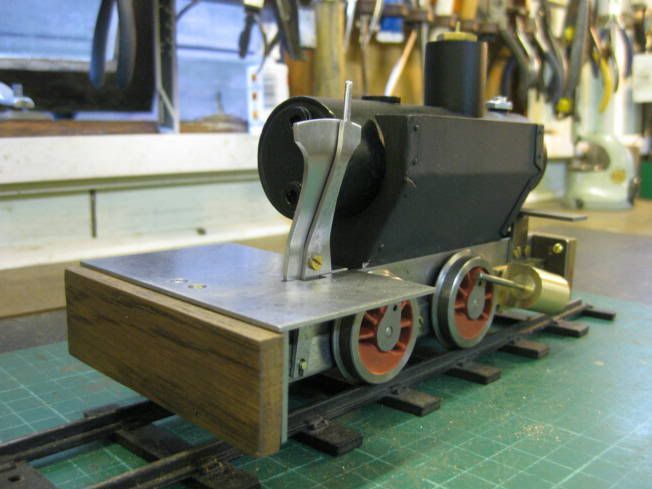
La Belle 'Anne' is gauge '0', 32mm or 1.1/4" which is the gauge of my layout and garden railway, it is also the most complete of Colin's drawings. La Belle 'Barbara' is the inside frame G1 version, it's overall length and height is the same as the other two versions but its an 1/2" wider to accommodate the larger gauge.
Regards Tony.
 
Hi,
Having finished another project I had some time so spent an hour or so on the locomotive. First lapping the cylinders.
LesBelleslappingcylinderLR.jpg

LesbelleslappedcylinderLR.jpg

Then making and fitting some front cylinder covers.
LesBellescylindercovermadeLR.jpg

New trunnions were made for the cylinders along with a long piston and rod to aid lining up the cylinders with the crank pin and coupling rod.
LesBellesliningupcylinderLR.jpg


Regards Tony.
 
Hi Tony,
a pretty little loco and a very nice built that you are describing now.
I agree that having removable wheels is a must but a hole through the wheel tyre!
May I suggest a longer set screw that comes right to the surface and mask somewhat this hole.
I use sometimes a cylindrical nut to fix wheels on threaded axle, a less conspicuous result IMO.
an interesting topic as usual with your posts.
cheers
Zephyrin
 
'

Nice project, Tony. As someone familiar with your write-ups, I see the same attention to detail
I've come to know in your builds. All well done.

Don't know why you're having trouble with the length of your posts. I don't know of a limit for the
size of the post on this forum, and have done many myself that had 10-15 pics and lots of words.

Dean
 
Hi Dean,

Don't know why you're having trouble with the length of your posts. I don't know of a limit for the
size of the post on this forum, and have done many myself that had 10-15 pics and lots of words.


It is probably down to my ineptitude, if computers had calibrated hand wheels instead of keys I might do better.

The problem I have is when the typing gets a few lines past past the bottom of the box it will no longer show the line that is being typed. You can move the cursor down to see it but one key stroke and it disappears again. So when this happens I type blind and then move the cursor to see the results, but my geriatric brain can only handle so many lines. I can put with it if every body else can.

Hi Zephyrin,

I do intend to plug the holes in the wheels with something that can be removed to access the screws. I have used screw on wheels with a recessed screw to lock them but find them a little difficult to quarter.

Well no playing with machines today. Thankfully the heavy rain has stopped as we are to take Thomas along with other locomotives to entertain the public as our model club which has an open day today but I suspect the ground will be a bit of a quagmire.


At this point I am typing blind.

Regards Tony.
 
Hi Tony
I get the same thing
sometimes I end up with displaced pics and such cos I can not see the next line
Thank u for reporting it, cos its very annoying. :bow:
 
I used to have the same problem, but it's not happening anymore. I think it probably has to do with the browser. My problem may have been fixed when I upgraded to IE9. For a while I was composing my messages in notepad or word, then just copying and pasting into the browser. Have you tried using a differen browser?

Chuck
 
Hi Chuck,
I used to have the same problem, but it's not happening anymore. I think it probably has to do with the browser. My problem may have been fixed when I upgraded to IE9. For a while I was composing my messages in notepad or word, then just copying and pasting into the browser. Have you tried using a different browser?
Many thanks for the information but my computer skills are limited. I will wait until our son visits who knows about these things to see what can be done.
I had an hour or so while the wife was away shopping. So started on fabricating a flame guard for the boiler using some recycled sheet steel.
LesBellesflameguard001LR.jpg

LesBellesflameguard002LR.jpg

LesBellesflameguard003LR.jpg

LesBellesflameguard004LR.jpg

LesBellesflameguard005LR.jpg

LesBellesflameguard006LR.jpg

LesBellesflameguard007LR.jpg


Might get a bit more done tomorrow.
Regards Tony.
 
Tony Bird said:
Hi Dean,

Don't know why you're having trouble with the length of your posts. I don't know of a limit for the
size of the post on this forum, and have done many myself that had 10-15 pics and lots of words.


It is probably down to my ineptitude, if computers had calibrated hand wheels instead of keys I might do better.

The problem I have is when the typing gets a few lines past past the bottom of the box it will no longer show the line that is being typed. You can move the cursor down to see it but one key stroke and it disappears again. So when this happens I type blind and then move the cursor to see the results, but my geriatric brain can only handle so many lines. I can put with it if every body else can.

Hi Zephyrin,

I do intend to plug the holes in the wheels with something that can be removed to access the screws. I have used screw on wheels with a recessed screw to lock them but find them a little difficult to quarter.

Well no playing with machines today. Thankfully the heavy rain has stopped as we are to take Thomas along with other locomotives to entertain the public as our model club which has an open day today but I suspect the ground will be a bit of a quagmire.


At this point I am typing blind.

Regards Tony.


I have the same issue Tony...I'll just have to update my browser like chuck did

Dave
 
Hi,
Finished making the flame guard today.
LesBellesflameguard008LR.jpg

LesBellesflameguard009LR.jpg

LesBellesflameguard010LR.jpg

LesBelles011LR.jpg

LesBellesflameguard011LR.jpg

LesBellesflameguard012LR.jpg

Not sure what I will make next, possibly the burner. At the moment the locomotive is very nose heavy and the burner will help to balance it. I still expect to have to ballast the rear of the locomotive to get equal weight on each wheel.
Regards Tony.
 
Hello Again,
Started on the burner but not before painting the flame guard with VHT paint and curing it in an oven. Best done when the domestic authorities are away.
LesBellesflameguard013LR.jpg

To get some weight to the back of the locomotive the burner's meths tank is being made from thick wall square section brass tube rather than being bent up from brass sheet. Colin as far as I know didn't make any meths fired locomotives only ones using gas. He acknowledges in his writings that the burner is to someone else's design. The tank can be filled from either side the filling tube not being used is the vent to allow air out. I have made many meths tanks but not for a long time. I prefer a filling system that allows the removal of meths and the tank fitted with an over flow pipe. With a full tank of meths as the tank gets hot which it does the meths expands can flood the burners and catch fire, youngsters watching will be entertained but it does little for the paint work. With the tanks I make the filling tube goes to the bottom of the tank so if you suck back with the syringe you can empty most of the meths from the tank. The tank is also fitted with an overflow pipe that drains well out from the back of the locomotive. In use the tank is filled using a syringe until meths comes out of the over flow pipe and a couple of cc's are sucked back out of the tank, this reduces the chance of fire. A photograph of one of my tanks as fitted to a Mamod locomotive replacing the fuel pellet tray.
LBMamodBurnerLR.jpg

I will continue in next post.

Regards Tony.
 
Hi,
LBMamodBurnerLR.jpg

I'm sorry I have made the photograph a little small. The photograph shows the burner with its tank. The small pipe coming out of the side of the tank is the overflow, the pipe coming out of the top of the tank is for filling. It has three burner tubes the centre one capped as the two others produce enough heat. There are also two heat/draft shields fitted to the meths supply tube. Photographs showing the progress made today on making a meths tank.
LBBurner001LR.jpg

LBBurner002LR.jpg

LBBurner003LB.jpg

LBBurner004LR.jpg

LBBurner005LR.jpg

LBBurner006LR.jpg

LBBurner007LR.jpg

LBBurner008LR.jpg

LBBurner009LR.jpg

LBBurner010LR.jpg

I will post some more later in the week.
Regards Tony.
 
Coming along well Tony :)

I like your tips on the filler and overflow pipes for the meths tank; definitely something to keep in mind - thank you! I've learned the hard way that spilled meths and tracks with plastic ties don't mix well either ::)

Kind regards, Arnold
 
Great job Tony. Colin Binnie was one of the greats in the Gauge 0 and Gauge 1 business. Yours will be a great running engine.
 
Hi,
Continued work on burner. K&S brass and copper tubes are used being silver soldered into the tank. Photographs of work done so far follow. While waiting for the tank/tubes to clean up in the pickle thoughts went on to the next part to be made, possibly the chimney which also holds the boiler to the chassis. While looking at the drawings it was noticed that Colin had intended that there would be no regulator the speed/forward and reverse being controlled by the reversing lever. The incomplete drawings show the position of the reversing lever but not how it would be connected to the reversing disc. Given the design of the locomotive this might effect the size and position of the meths tank which Colin might have had to alter. So work on the burner will cease for the moment while thoughts are directed at the reversing assembly.
LbBurner011LR.jpg

LBBurner012LR.jpg

LBBurner013LR.jpg

LBBurner014LR.jpg

Might be some time before the next post!
Regards Tony.
 
Hi,
Had a play with some drawings to see if I could come up with a way of connecting the reversing lever to the reversing disc with out getting in the way of the burner and didn't get anywhere. I felt a bit like a traveler on asking directions being told that if you want to go there don't start from here!
So I decided to fit the footplate to see if that helped with the ideas. I normally fit flame and wind guards to the burner but decided to fit them as stretchers for the frame and one could be used to secure the footplate, the other to hold the front end of the burner. The burner would then be easier to remove for adjustment. Work done today follows. Still no ideas yet for the reverser connection.

LBStretcher001LR.jpg

LBStretcher002LR.jpg

LBStretcher003LR.jpg

LBStretcher004LR.jpg

LBStretcher005LB.jpg

LBStretcher006LR.jpg

LBStretcher007LR.jpg

LBStretcher008LR.jpg

LBStretcher009LR.jpg

LBFootplateLR.jpg


Regards Tony.
 
Hi,

I think I might of found away of connecting the reversing lever to its disc. First it requires making another reversing disc. Photographs follow.

LBReverseDisc001LR.jpg


LBReverseDisc002.jpg


LBReversingDisc003LR.jpg


LBReversingDisc004LR.jpg


LBReversingDisc005LR.jpg


LBReversingDisc006LR.jpg


LBReversingDisc007LR.jpg


Sums now need to be done to work out the lengths of the levers required.

Regards Tony
 
Great work Tony
keep it up :bow:
Pete
 
Hi,
A mixed day playing. Decided to rough out the reversing stand and lever which turned out quite well until I fitted the boiler! A bit of an issue, the stand is too far foward, Colin hadn't drawn a plan so something will have to be worked out. Wooden buffer beams have been fitted to protect fingers while operating the locomotive. Photogrphs of work done today.
LBmakingwoodenbufferbeamLR.jpg

LBReversing001LR.jpg

LBReversing002LR.jpg

LBReversing003LR.jpg

LBReversing004LR.jpg

LBReversing005LR.jpg

LBReversing006LR.jpg

LBReversing007LR.jpg


Regards Tony.
 
Hi,
Yesterday made the connecting lever and resolved the issue with the reversing lever stand touching the boiler. Started with bending some sheet steel to make a piece of 10mm angle. This angle was then worked on using a piercing saw and file to make the connection between the brass pins fitted on the reversing lever and the reversing disc. There were a couple of possibilities to resolve the issue of the reverser stand and the boiler. Move the stand outwards which would make the connection of the lever and disc a bit more unsightly. Move the stand backwards were it would partially block the door way. Colin might have re drawn. I decided to bend both the reversing stand and lever, I'm sure there will be a prototype president somewhere, there usually is with narrow gauge locomotives. Now back to the burner I think. Photographs and a video follow.

LBReversing008LR.jpg


LBReversing009LR.jpg


LBReversing010LR.jpg


LBReverse012LR.jpg


VIDEO


LBReverse016LR.jpg


LBReverse015LR.jpg


LBReverse014LR.jpg


Regards Tony.
 
Back
Top