


- Joined
- Jun 4, 2008
- Messages
- 3,285
- Reaction score
- 630
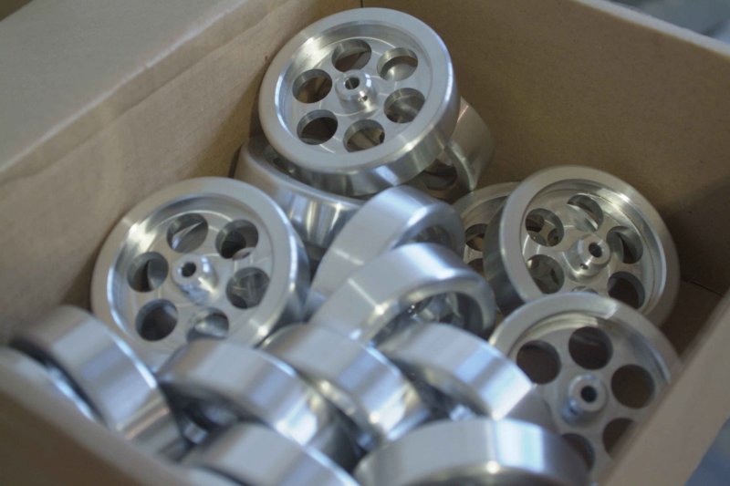
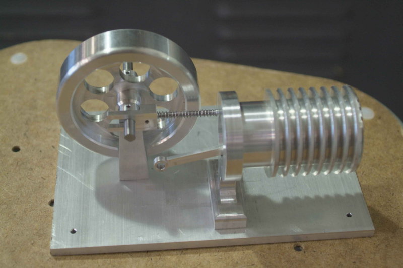
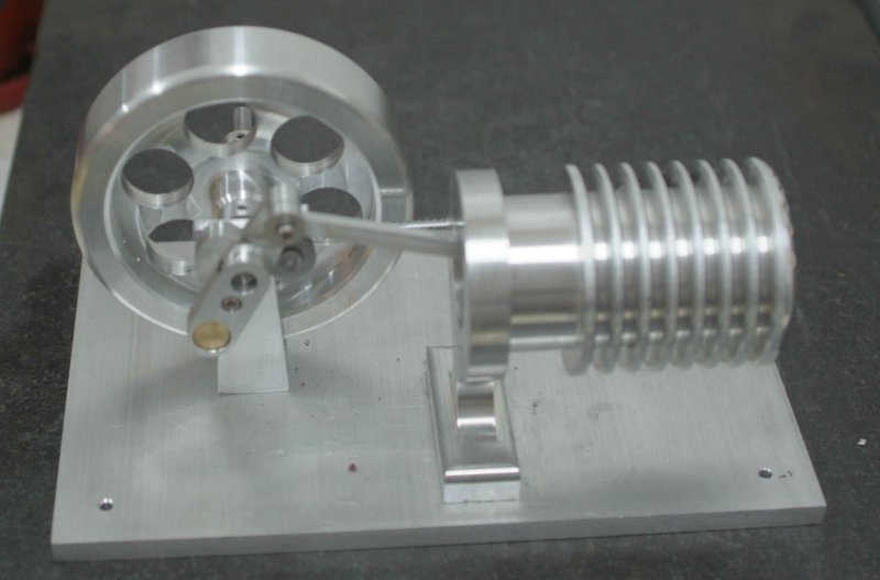
For my final machining class at the local votech school, a team of 6 people will attempt to build 20+ examples of the Duclos "Fire Eater" Stirling engine. The goal is for each of us to end up with an engine, and then to have lots of extras to give to local highschools as recuitment aids for the machining courses.
Here's a HMEM thread showing a running engine: http://www.homemodelenginemachinist.com/index.php?topic=3568.0
We are divided into three groups of two and each group will be responsible for different parts as we progress. The parts will be made using the Haas CNC lathes and mills, with CAD/CAM done on MasterCam. For the most part we will try to make the parts as drawn. One learning objective of the course is to be able to design the necessary fixturing to produce multiple parts efficiently. Another is to develop teamwork so that mating parts do go together properly. I seem to be the only one in the class who has ever built a model engine, so I'm aware that getting separate parts to work flawlessly right off the machines can be quite a challenge. So the fact that we will be using precision CNC gear will be interesting to me to see how well it works. My teammate is another old retired guy like me who hasn't taken any of the CNC classes, so I will be doing all the Cad/CAM work for our parts.
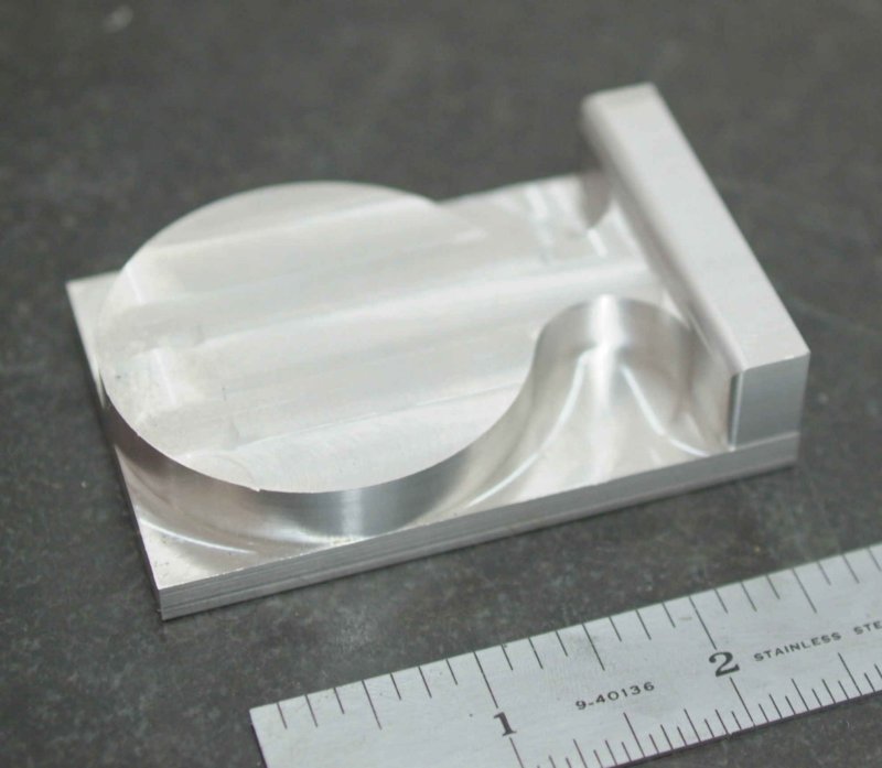
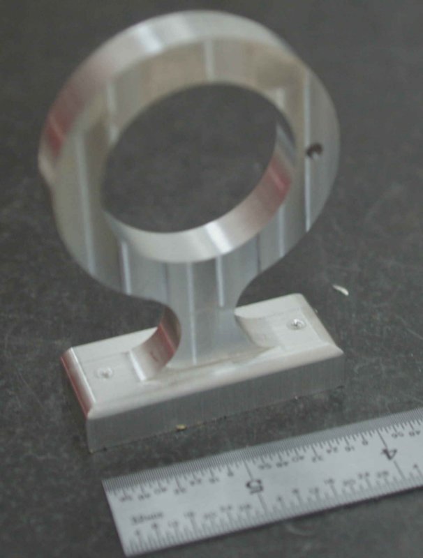
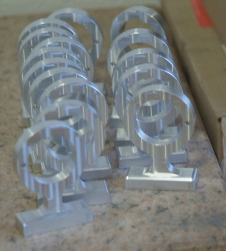
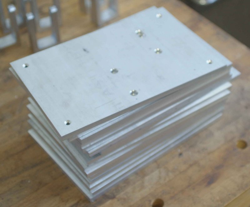
Our first part is the the cylinder pedestal. While I spent the first class period on the computer, he cut 24 pieces of aluminum stock 3/4 x 2 x 3 and deburred them. To make the pedestal I needed 3 drawings. The first machines the profile on one side leaving 1/16" for holding in the milling vise. The second drawing is for cutting soft jaws for the vise to hold the parts from step one, and the third drawing machines the reverse side of the pedestal plus the holes for the cylinder and timing shaft. It will still need tapped holes in the base for mounting, but I'm not sure yet how we'll do that. Duclos specifies a press fit between the pedestal and the cylinder, but we are thinking about doing a shrink fit.
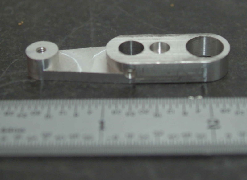
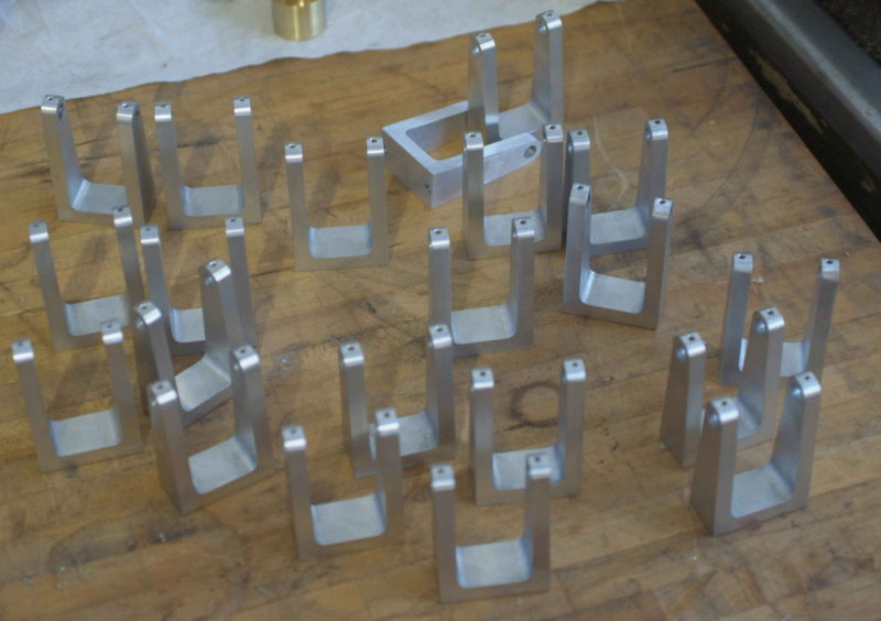
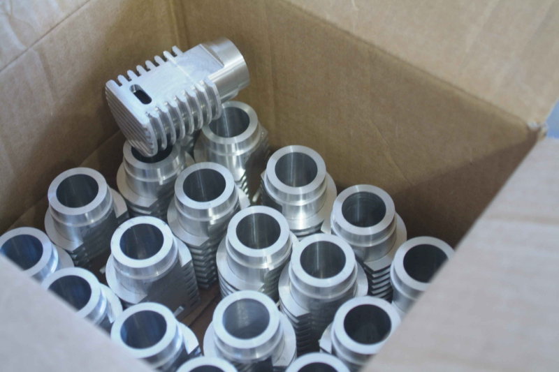
Our class meets Monday and Wednesday evening from 5:30 to 9:30. I hope to get the first side of the pedestal machined on Wednesday, and produce some pictures as well. Another team is making the cylinders on the lathe, so we might be able to see some other parts too. Team three is starting with the bearing bracket.
Here's a HMEM thread showing a running engine: http://www.homemodelenginemachinist.com/index.php?topic=3568.0
We are divided into three groups of two and each group will be responsible for different parts as we progress. The parts will be made using the Haas CNC lathes and mills, with CAD/CAM done on MasterCam. For the most part we will try to make the parts as drawn. One learning objective of the course is to be able to design the necessary fixturing to produce multiple parts efficiently. Another is to develop teamwork so that mating parts do go together properly. I seem to be the only one in the class who has ever built a model engine, so I'm aware that getting separate parts to work flawlessly right off the machines can be quite a challenge. So the fact that we will be using precision CNC gear will be interesting to me to see how well it works. My teammate is another old retired guy like me who hasn't taken any of the CNC classes, so I will be doing all the Cad/CAM work for our parts.
Our first part is the the cylinder pedestal. While I spent the first class period on the computer, he cut 24 pieces of aluminum stock 3/4 x 2 x 3 and deburred them. To make the pedestal I needed 3 drawings. The first machines the profile on one side leaving 1/16" for holding in the milling vise. The second drawing is for cutting soft jaws for the vise to hold the parts from step one, and the third drawing machines the reverse side of the pedestal plus the holes for the cylinder and timing shaft. It will still need tapped holes in the base for mounting, but I'm not sure yet how we'll do that. Duclos specifies a press fit between the pedestal and the cylinder, but we are thinking about doing a shrink fit.
Our class meets Monday and Wednesday evening from 5:30 to 9:30. I hope to get the first side of the pedestal machined on Wednesday, and produce some pictures as well. Another team is making the cylinders on the lathe, so we might be able to see some other parts too. Team three is starting with the bearing bracket.
 (continuing with your theme !!)