
You are using an out of date browser. It may not display this or other websites correctly.
You should upgrade or use an alternative browser.
You should upgrade or use an alternative browser.
Casting Engine Components For a Twin
- Thread starter Artie
- Start date


Help Support Home Model Engine Machinist Forum:
This site may earn a commission from merchant affiliate
links, including eBay, Amazon, and others.
Hiya Tel, I think you are on the money there, combined with another idea from Modmodder.. Make the rivets in thin strips of brass which can then be soldered in place simulating the overlapped rivetted panels. Ill give it a go and get back with the results.
Just about finished the rods. Milled 2.5 mm off each side of the rod beams to bring them down to 6mm (from 11mm), the cheeks of the big ends are still 11mm. I used a jig made from a lump of aluminium left over from a casting experiment. Drilled and tapped it for the rod length, bolted a rod down and did the milling on one side, removed it did the other rod the same and then milled a 2.5mm deep pocket where the big end sits to allow the rod beam to sit flat on the plate and then did the other sides of both rods.
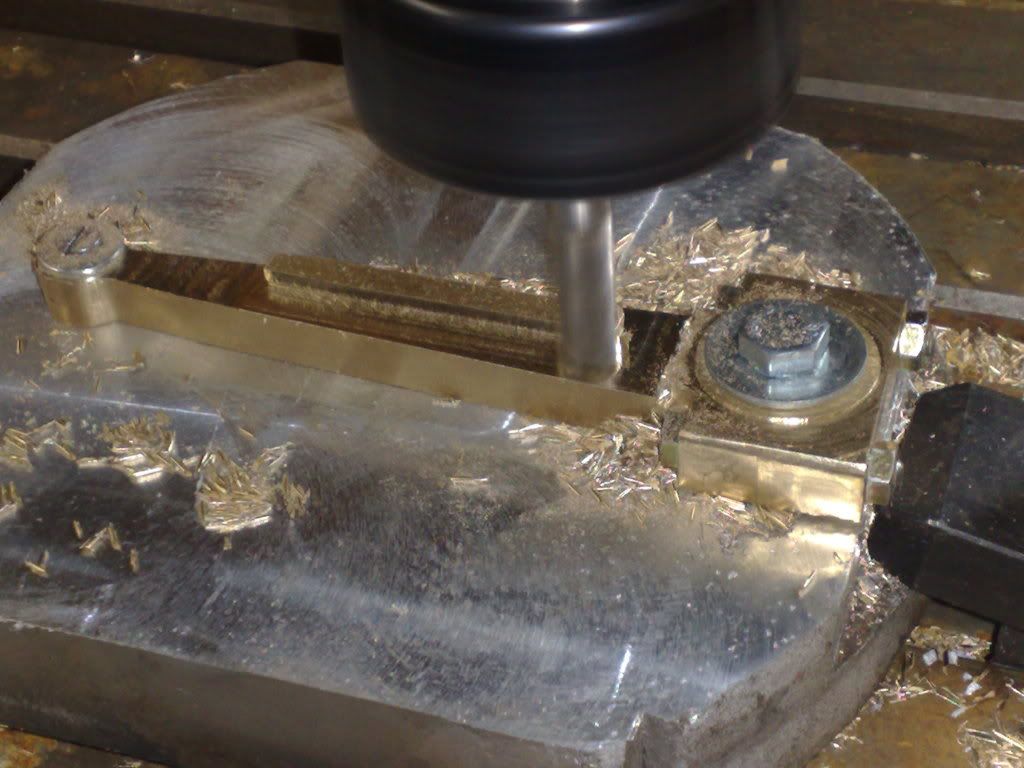
And the almost finished product
, the gudgeon pins ar a press fit into the slide mount and free within th erod, like normal car stuff. I am doing this because you can see how much clearance is avalable when th esider moves up to teh oiler cups. I wont actually press anything, heating and freezing and loctite will allow hand assembally.
And while I love working with the mill and lathe, I also love handworking my bits. So I do a lot of filing and sanding in the final shaping stage. Dont think for a minute that the rod beams came off the tool that smooth!
Now working on the reversing linkage... seems like Kvom has answered a few questions I had by posting his pics...thanks mate! Im pretty much following Edgar T.'s plans to the letter here... its an area I dont have much (any?) experience in... so Ill play on something else at another time....
Cheers Rob
Just about finished the rods. Milled 2.5 mm off each side of the rod beams to bring them down to 6mm (from 11mm), the cheeks of the big ends are still 11mm. I used a jig made from a lump of aluminium left over from a casting experiment. Drilled and tapped it for the rod length, bolted a rod down and did the milling on one side, removed it did the other rod the same and then milled a 2.5mm deep pocket where the big end sits to allow the rod beam to sit flat on the plate and then did the other sides of both rods.
And the almost finished product
, the gudgeon pins ar a press fit into the slide mount and free within th erod, like normal car stuff. I am doing this because you can see how much clearance is avalable when th esider moves up to teh oiler cups. I wont actually press anything, heating and freezing and loctite will allow hand assembally.
And while I love working with the mill and lathe, I also love handworking my bits. So I do a lot of filing and sanding in the final shaping stage. Dont think for a minute that the rod beams came off the tool that smooth!
Now working on the reversing linkage... seems like Kvom has answered a few questions I had by posting his pics...thanks mate! Im pretty much following Edgar T.'s plans to the letter here... its an area I dont have much (any?) experience in... so Ill play on something else at another time....
Cheers Rob
Logically, now that the conrods almost finished its time to start the crankshaft. Im starting with the cheeks and this is bigger than you would think. Two storys here one is the crank, the other is recommissioning an old friend. More in a moment.
Firstly some 60mm stock was dragged out. No idea what steel it is... just steel. Machines and cuts ok. Trimmed the oxy end off.
Have I mentioned that I love the old power hacksaw?
Trued up in the lathe and centre drilled, sized up and the drilled for full depth of 60mm using incrimental drill sizes 4 through to 12mm.
Marked up and drilled the big end journal and the radius of the cheeks as well.
By now the new table is covered in crap... as it should be...
Now the second story, the horizontal mill was put into storage about 15 years ago. The apprentice was using the pallet jack and ran it into the x axis feed handle completely smashing it off the machine. This was put aside for awhile until I got round to it. Eventually the broken parts were lost and then the machine was put into storage and pretty much considered to be scrap metal.
About a year ago I dragged an old box out from under a bench...bugger me the missing broken bits. Cept for the part which bolted to the table itself. I made a plate up, machined the gearbox to suit and had teh entire machine rewired... tonight was its first start up (the electrician finished as i was finishing drilling the holes)... away we went.... a momentus day for the old girl...
Slices into the steel like butter...
Rotate the shaft and cut the slight angles...
Cut across the shaft to free the slices and we have.....
Final sizing in the mill tomorrow and then slice the plates off in the power hacksaw...did I mention that I love this old machine?
This has saved an absolute heap of time and agro removing this metal with the mill. The mill is a big unit but still doesnt like cutting large chunks of steel.
More tomorrow..public holiday here...
Cheers
Rob
Ive been blessed the last few days with fairly good time in the shop. As a result Ive actually got something done.... its nice to have something to show you guys. The crank cheeks are just about finished.... heres the rest of the journey...
Back into the mill after lunch and tidied up the horizontal mill cuts. Just blended them into teh previously drilled holes really... then inot teh old power hacksaw and cut off teh four segments....
Made a mandrel with a spgot the internal size of the cheeks, tapped a retaining bolt and away we go,
firstly in to the mill to do the reliefs...
thought I had pressed the preview button but posted instead.. all good...carrying on...
Then changed to the big end hole to do the round off...
Its starting to look like its coming together....
Im in my regular work away from home period shortly so not much will happen for a couple of weeks.
Cheers Rob
Then changed to the big end hole to do the round off...
Its starting to look like its coming together....
Im in my regular work away from home period shortly so not much will happen for a couple of weeks.
Cheers Rob
Artie said:perhaps a little larger than you would normally see around these parts...
Cheers
Rob
I would even go so far to say monstrous.
Its coming along nicely
Hi Tmuir... monstrous is good I hope..?? :- I think it is in this case... it all fits its intended purpose.. ;D
Im at somewhat of a crossroads right now... I need the boiler to be in place to go on. While im doing this there area few other bits I can do but most is reliant upon this.
Decision decisions... I have materials for both a steel and a copper boiler... so far I have swayed back and forth about 2475 times... each has its advantages and disadvantages....
Right now Im thinking copper...
Mainly because I can silver solder it myself, whereas a steel unit requires a certified boiler maker to weld it. The drawn (seamless) steel tubing I have is a little too large for the engine aesthetically and the codes requirements for the construction of a copper boiler are a whole lot less onerous as this size tubing falls into the subminiature category where as the steel size is in the miniature category.
The drawbacks of the copper are that it is a fairly small capacity and will require topping up for any extended periods of running unless I build the pump Edgar W, lists in his plans. I am making provision for this by building the eccentic onto the crank. It wont be accessible afterwards and I dont really want to do a split eccentic.
The capacity of teh steel boiler is what is making me keep coming back to it (therefore the simplicity....ie no pump or water reservoir in the hull).
However..copper it is... I think.....
A couple of pics of the mock up I have been fiddling with to determine the 'looks' of the unit..... ignore the timber blocks...
Copper...(verdis and all!)... the copper boiler is a little small in looks and this will allow me to put a cover over it with teh scale details added and this will also act as an insulator retaining the heat to a degree and increasing it efficiency..
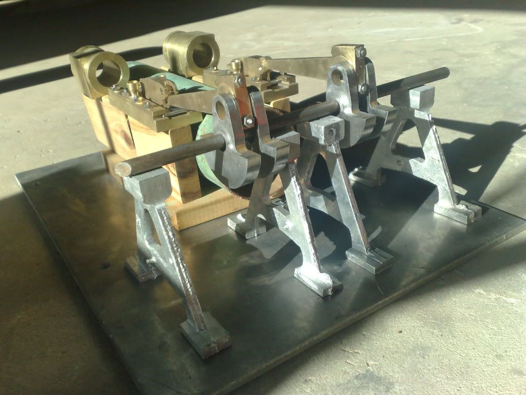
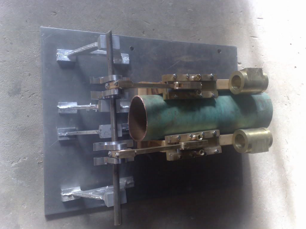
Steel...
Copper copper copper...
Cheers Rob
Im at somewhat of a crossroads right now... I need the boiler to be in place to go on. While im doing this there area few other bits I can do but most is reliant upon this.
Decision decisions... I have materials for both a steel and a copper boiler... so far I have swayed back and forth about 2475 times... each has its advantages and disadvantages....
Right now Im thinking copper...
Mainly because I can silver solder it myself, whereas a steel unit requires a certified boiler maker to weld it. The drawn (seamless) steel tubing I have is a little too large for the engine aesthetically and the codes requirements for the construction of a copper boiler are a whole lot less onerous as this size tubing falls into the subminiature category where as the steel size is in the miniature category.
The drawbacks of the copper are that it is a fairly small capacity and will require topping up for any extended periods of running unless I build the pump Edgar W, lists in his plans. I am making provision for this by building the eccentic onto the crank. It wont be accessible afterwards and I dont really want to do a split eccentic.
The capacity of teh steel boiler is what is making me keep coming back to it (therefore the simplicity....ie no pump or water reservoir in the hull).
However..copper it is... I think.....
A couple of pics of the mock up I have been fiddling with to determine the 'looks' of the unit..... ignore the timber blocks...
Copper...(verdis and all!)... the copper boiler is a little small in looks and this will allow me to put a cover over it with teh scale details added and this will also act as an insulator retaining the heat to a degree and increasing it efficiency..
Steel...
Copper copper copper...
Cheers Rob
Just FYI, subminiature regs require the boiler to be 75mm dia or less, 1000cc capacity or less and an operating pressure of up to 75psi. The premise is that these 'little' boilers wont have the capacity to be used in trains which can tow passengers or an engineer..therefore they wont be in extremely close proximity to persons when they explode... (thats my extrapolation.. ;D).
Therefore they are a lot simpler to build...
Therefore they are a lot simpler to build...
Artie said:Hi Tmuir... monstrous is good I hope..?? :-\ I think it is in this case... it all fits its intended purpose.. ;D
Yes Monstrous is good. ;D
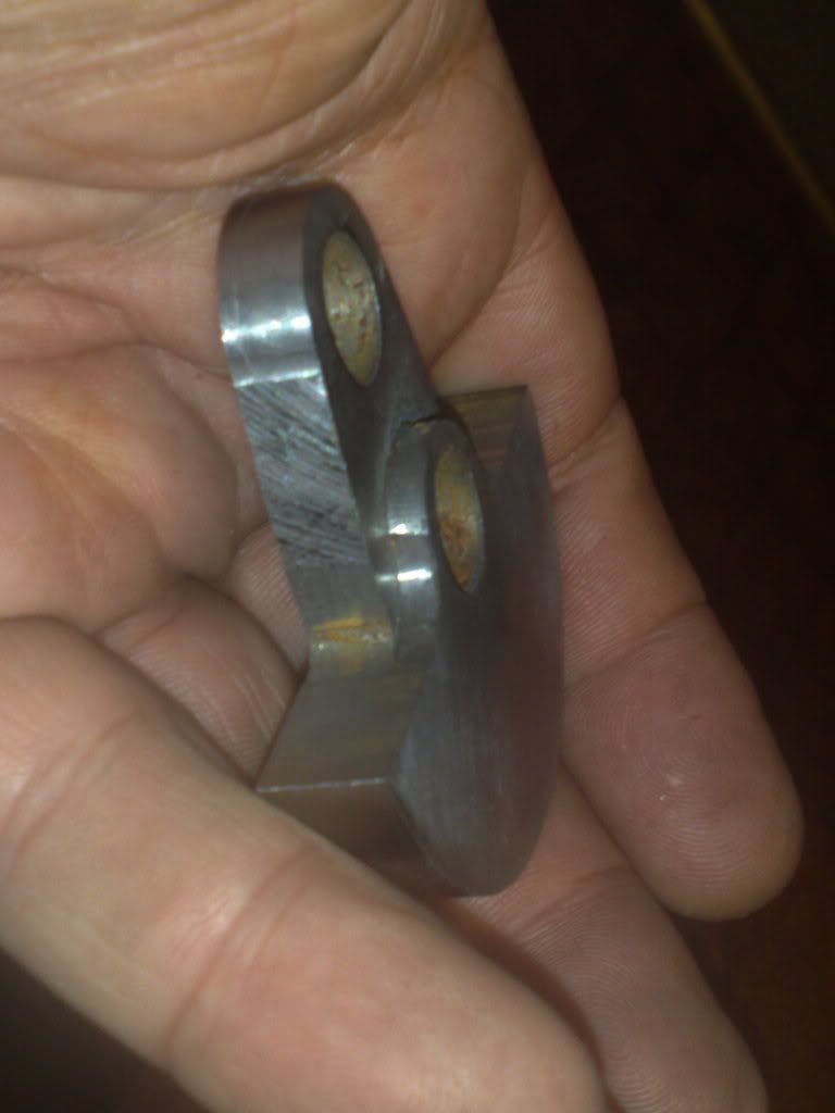
I've been enjoying following your build and didn't realise just how big it was until you held that last part in your hand.
I personally would prefer a copper boiler for no other reason than rust isn't an issue.
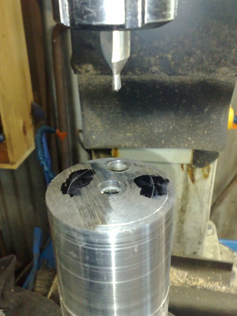
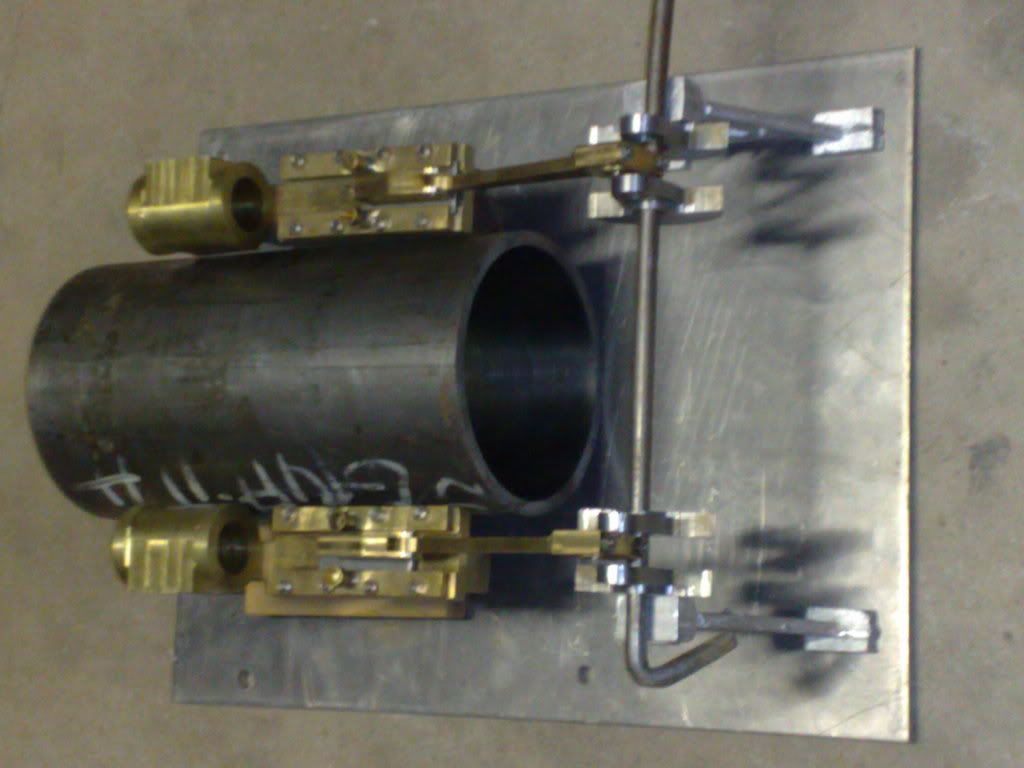
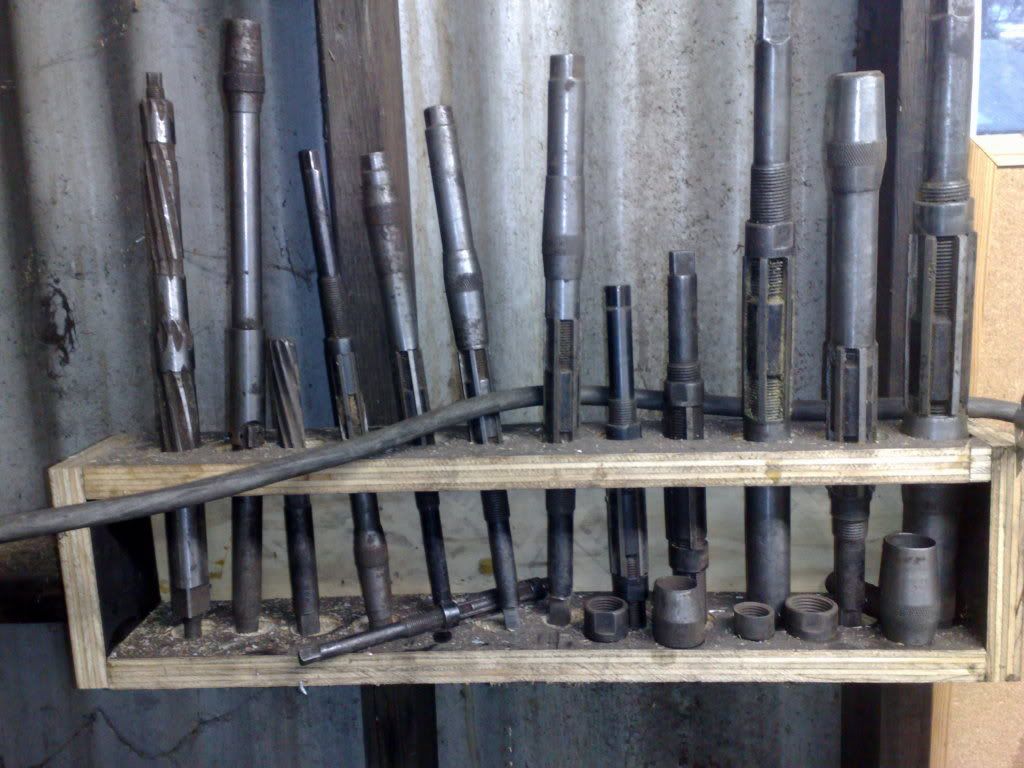
A little update, not too much, decided to try out Bogs (thanks John) d bit reamer design. Its my first ever attempt at such a tool so it was a learning curve and fun. The fact that it was a success is also a bonus.
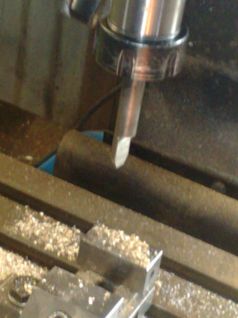
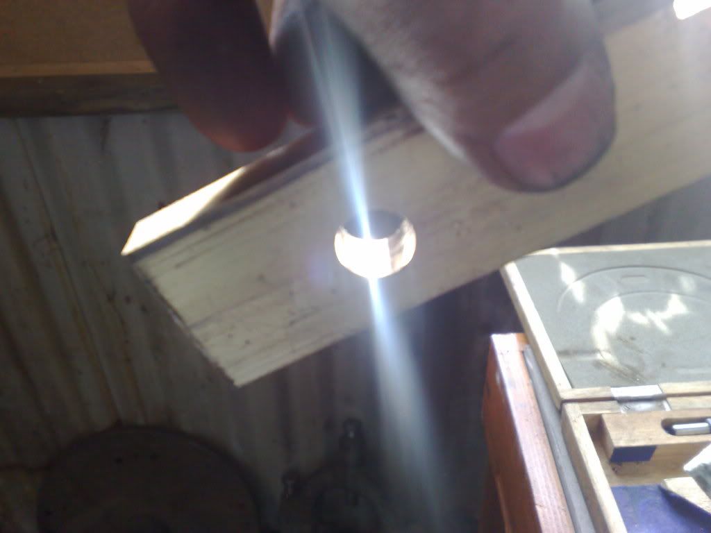
I took the shot with the reflection on purpose... that was a test piece and the finish was extraordinary. Worked a charm. reamed the brass conrods out and then did the crank cheeks. I used a product over here called bright steel, simply a slightly better quality mild steel rod. Sized it up and used a hardening compound called Hardite. This is a tin we got from the fellow who owned the workshop before I and my partner bought it. It was ancient then and that was back in 1985.
Anyway, the resultant case hardening was ok for the brass but not quite good enough for the steel. It did the job but I had to resharpen the tool after each hole. I call this a success and the holes are damned accurate....
Also decided to add a little more detail to the conrods and milled the centres out by 2 mm leaving a centre thickness of 2mm (overall was 6mm)
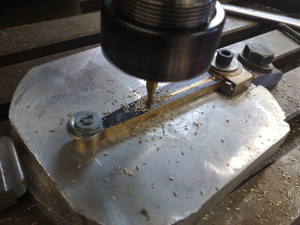
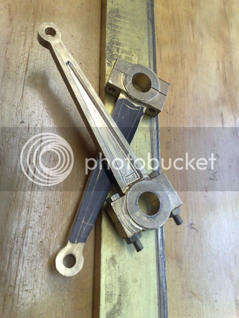
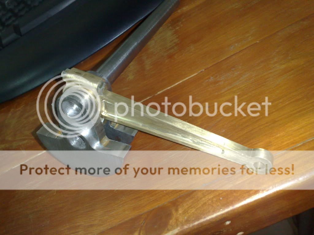
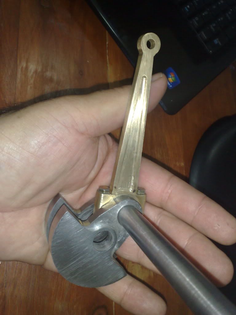
Now just got to do a little sanding and filing to remove the tool marks. I used the ball nosed cutter for the entire process but I realy should have profiled the sides then changed to an end mill to remove the centre material. It left a lot of small marks which now need removing (see pics).
I like the 'real engine' effect though and its certainly only bling detail... but i enjoyed myself.....
The exercise in reamer manufacture was an experiment, because these are sitting on the wall behind the mill, it was a case of.."because I can..."....
Until next installment...
Rob
I took the shot with the reflection on purpose... that was a test piece and the finish was extraordinary. Worked a charm. reamed the brass conrods out and then did the crank cheeks. I used a product over here called bright steel, simply a slightly better quality mild steel rod. Sized it up and used a hardening compound called Hardite. This is a tin we got from the fellow who owned the workshop before I and my partner bought it. It was ancient then and that was back in 1985.
Anyway, the resultant case hardening was ok for the brass but not quite good enough for the steel. It did the job but I had to resharpen the tool after each hole. I call this a success and the holes are damned accurate....
Also decided to add a little more detail to the conrods and milled the centres out by 2 mm leaving a centre thickness of 2mm (overall was 6mm)
Now just got to do a little sanding and filing to remove the tool marks. I used the ball nosed cutter for the entire process but I realy should have profiled the sides then changed to an end mill to remove the centre material. It left a lot of small marks which now need removing (see pics).
I like the 'real engine' effect though and its certainly only bling detail... but i enjoyed myself.....
The exercise in reamer manufacture was an experiment, because these are sitting on the wall behind the mill, it was a case of.."because I can..."....
Until next installment...
Rob
I cant believe it was May when I last posted in here! Work has stalled for a time on the engine but I do have reasons (excuses??). Working away from home takes half of the preceding week to get ready to go, 1 week in the coastal office and the another half week tidying up when I retrurn so basically 2 weeks of every 4 are lost due to primary focus on WORK (another nasty 4 letter word...).
The QCTP tool holders took longer than I had thought and so did the repairs and learning curve for the Shaper. Ive also cast up a heap of brass into ingots for the next stage so its not too far away, while i was doing that my hi presure gas regulator died so I had to order a new one etc etc etc.
Some may ask why I work 600kms from home (particualrly when there no flights available to my other office and I have to drive). Several reasons, I sign the company cheques (thats a pretty big motivator), the coastal office really does carry the company so it gets a lot of attention, I'm buying a block of land about 2kms away from the office (so the commute will be reversed in a couple of years) and...... and ......... this is the view from the bar next door to the office at about 5.30pm.....


And.... this is in the depths of our winter..... ahhh....
The QCTP tool holders took longer than I had thought and so did the repairs and learning curve for the Shaper. Ive also cast up a heap of brass into ingots for the next stage so its not too far away, while i was doing that my hi presure gas regulator died so I had to order a new one etc etc etc.
Some may ask why I work 600kms from home (particualrly when there no flights available to my other office and I have to drive). Several reasons, I sign the company cheques (thats a pretty big motivator), the coastal office really does carry the company so it gets a lot of attention, I'm buying a block of land about 2kms away from the office (so the commute will be reversed in a couple of years) and...... and ......... this is the view from the bar next door to the office at about 5.30pm.....
And.... this is in the depths of our winter..... ahhh....
Hey all, Im alive, no..... I know..... you didnt miss me....story of my life :noidea:
Havent had a lot of engine time for a variety of reasons. What time I have had has been making tooling and learning to operate the shaper, (love the shaper... ). ;D
Today I waved goodbye to lawns, painting, fence repair, car washing, travel and headed down to the shed...... its MY time......
What I have had is time to think about the parts which are next on the list.... eccentric sheaves and rods for the valve gear.
Ive decided not to use Edgar T Westburys design on this one for a couple of reasons, the main issue was the complexity. I think this thing could be made better, simpler.... remember im using the design as inspiration for my own engine.... Im not producing the engine verbatim....
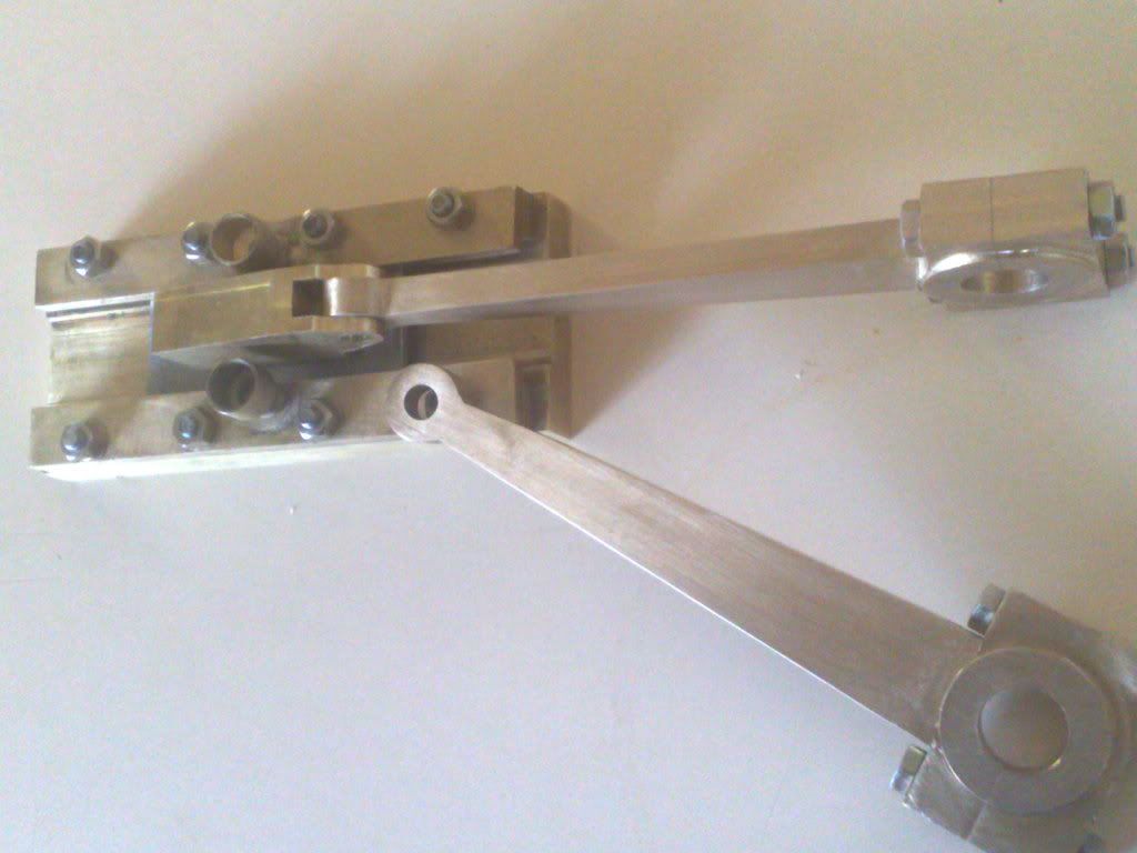
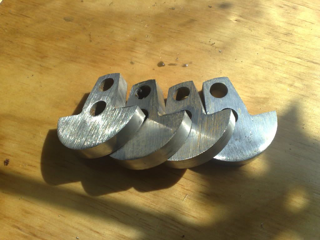
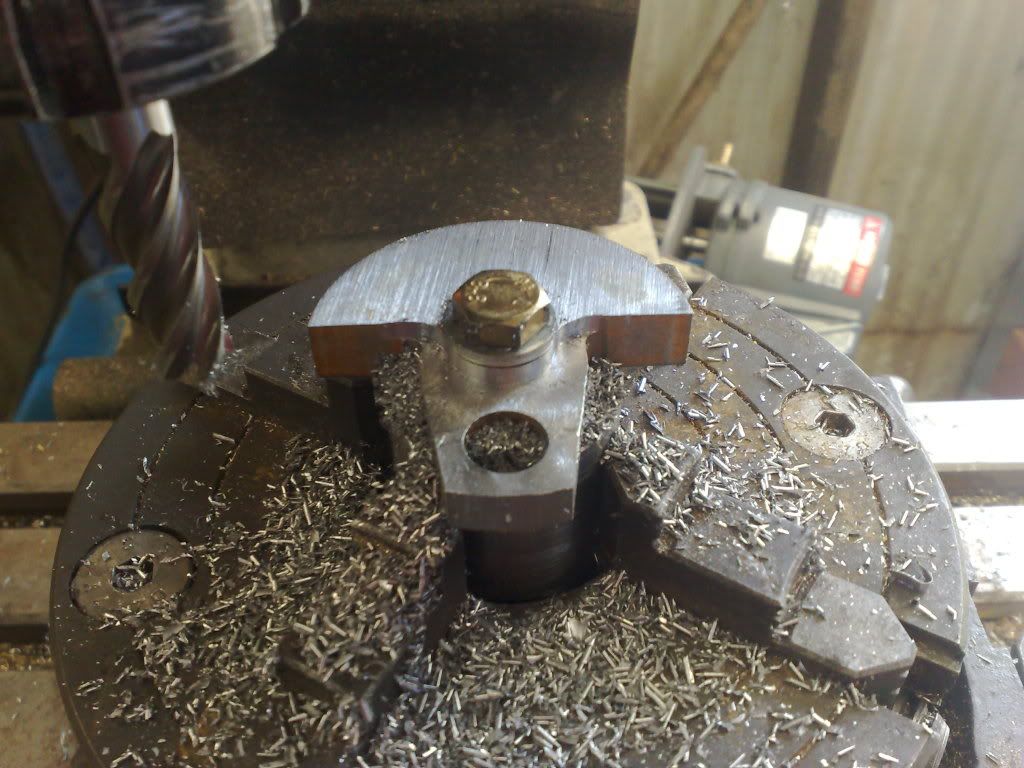
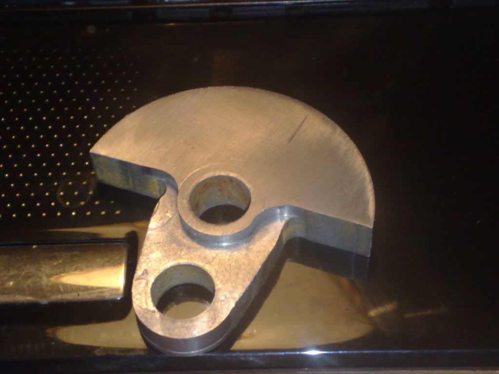
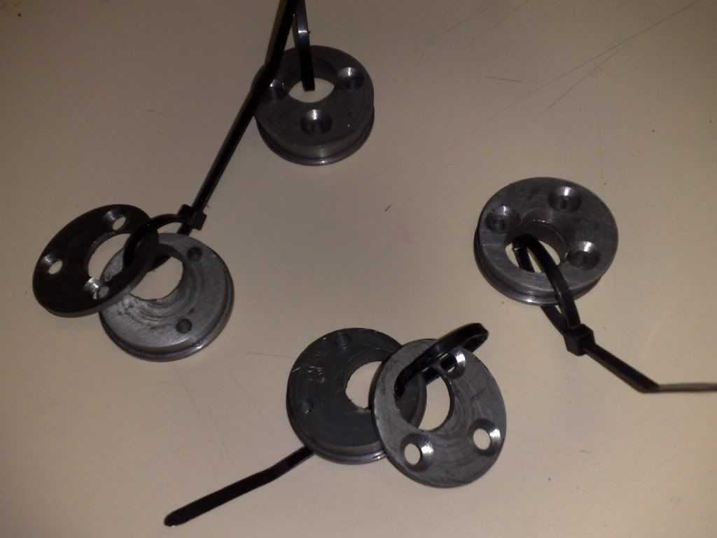
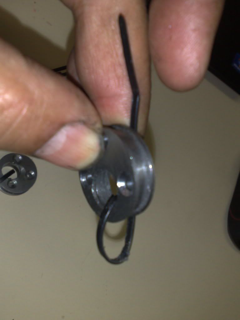
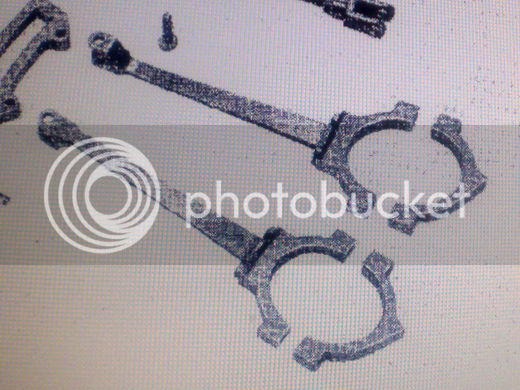
Ive decided to make the valve gear rods in one piece instead of three piece as per the plans. Im splitting the eccentric sheave to allow this, as per the pics that follow.... the eccentics.... (4 of)...
These are one piece by the plans so Ive used a removeable side plate held in place by three screws. This allows the rod to be a one piece unit with no removeable big end cap and as this is only 4mm wide... that would make it unecessarily fiddly...(IMO)
Im a great believer in simplicity and I dont like complex items for complexity's sake.... not saying thats Edgar's reasoning... I just think I have found another way that suits me.
So, by making this item with a removeable side plate...
I can make this item in one piece and less complex....
Hopefully tomorrow is the one piece valve rods (4 of), if I can get those done Ill be more than happy....
Its nice to be back... had a ball in the shop today... By the way...its amazing how much time lil parts can take to make.......
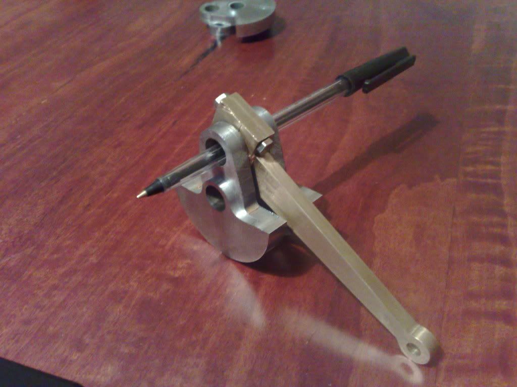
I should mention that I can do this because Ive turned the engine inside out... that is, the eccentric sheaves and valve rods are are outside the con rods, unlike the original design which has these hidden away in the centre of the engine.
In this way the one piece valve rods can be threaded onto the crankshaft and then onto the sheaves where as in the plans they MUST be the 3 piece design to allow assemby.
In my opinion, these reciprocating moving items are part of the mystique which makes these engines almost hypnotic.... why hide this detail away inside the frames?
Cheers Rob T Thm:
Havent had a lot of engine time for a variety of reasons. What time I have had has been making tooling and learning to operate the shaper, (love the shaper... ). ;D
Today I waved goodbye to lawns, painting, fence repair, car washing, travel and headed down to the shed...... its MY time......
What I have had is time to think about the parts which are next on the list.... eccentric sheaves and rods for the valve gear.
Ive decided not to use Edgar T Westburys design on this one for a couple of reasons, the main issue was the complexity. I think this thing could be made better, simpler.... remember im using the design as inspiration for my own engine.... Im not producing the engine verbatim....
Ive decided to make the valve gear rods in one piece instead of three piece as per the plans. Im splitting the eccentric sheave to allow this, as per the pics that follow.... the eccentics.... (4 of)...
These are one piece by the plans so Ive used a removeable side plate held in place by three screws. This allows the rod to be a one piece unit with no removeable big end cap and as this is only 4mm wide... that would make it unecessarily fiddly...(IMO)
Im a great believer in simplicity and I dont like complex items for complexity's sake.... not saying thats Edgar's reasoning... I just think I have found another way that suits me.
So, by making this item with a removeable side plate...
I can make this item in one piece and less complex....
Hopefully tomorrow is the one piece valve rods (4 of), if I can get those done Ill be more than happy....
Its nice to be back... had a ball in the shop today... By the way...its amazing how much time lil parts can take to make.......
I should mention that I can do this because Ive turned the engine inside out... that is, the eccentric sheaves and valve rods are are outside the con rods, unlike the original design which has these hidden away in the centre of the engine.
In this way the one piece valve rods can be threaded onto the crankshaft and then onto the sheaves where as in the plans they MUST be the 3 piece design to allow assemby.
In my opinion, these reciprocating moving items are part of the mystique which makes these engines almost hypnotic.... why hide this detail away inside the frames?
Cheers Rob T Thm:
Aw C'mon now Artie, of course we all missed you....... (like a stubbed toe :hDe") ;D
;D
I agree with you that some of the designs that are available and in print by some of the better known builders are just a bit over the top in terms of complexity. Sure they have eye catching qualities and charm etc, but when it comes down to actually making the tiny bits and bobs, one almost has to be a jeweler to fabricate them to spec. I like your approach to simplifying pieces in order to alleviate some, if not all, of the aforementioned stumbling blocks (is that how that digit got injured?) in order to achieve the same mechanical results. Welcome back!
BC1
Jim
;DI agree with you that some of the designs that are available and in print by some of the better known builders are just a bit over the top in terms of complexity. Sure they have eye catching qualities and charm etc, but when it comes down to actually making the tiny bits and bobs, one almost has to be a jeweler to fabricate them to spec. I like your approach to simplifying pieces in order to alleviate some, if not all, of the aforementioned stumbling blocks (is that how that digit got injured?) in order to achieve the same mechanical results. Welcome back!
BC1
Jim
zeeprogrammer
Well-Known Member
- Joined
- Mar 14, 2009
- Messages
- 3,362
- Reaction score
- 13
You were gone? :big:
HI Guys, yes Ive missed you all to, stubbed toes and all.... :big: :big:
Ahhh Jim Jim Jim..... of course I know you didnt mean that...oh? You did? Well I guess you sometimes have to be cruel to be kind... ;D
Carl, Carl? Carl who?.. I wasnt actually gone but was only dropping in to catch up infrequently, loving your loco by the way, glad you had no issues with the hydro after so much heartache with the boiler, soon you will be heavily into track building... I can just see it now..... "NO Carl you CANNOT run track through the bedroom.."
Sam, I think you can take the outside the box thing a bit to far at times, but I have always been a minimilist and given the opportunity, this just made sense.
Ill try and make progress a little more regular.
Rob
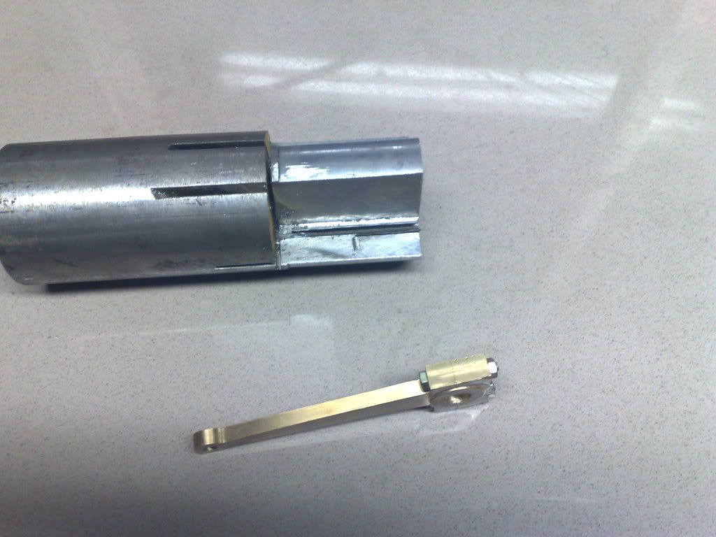
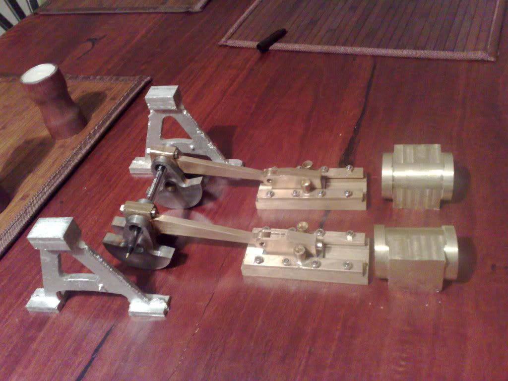
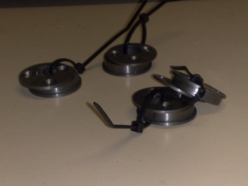
Hi all, the eccentrics are finished and pictured here mounted on a piece of the rod to be used for the crank. Some finishing required to remove fine burs and smooth/polish it all out. A 4mm grub screw locks them to the shaft. I had to make a new tap holder for the tapping tool as this size tap had a larger shaft than the first 4BA tap (see here http://www.homemodelenginemachinist.com/index.php?topic=8854.0).
I didnt take pics but the first eccentric took 45 mins (make tool etc) and the rest took only 10 mins each to finish.
This required setting the eccentric to its required orientation, mill a small flat at 4mm, then drill to 3.2mm and the tap in the holder to 4mm by 0.75mm pitch.
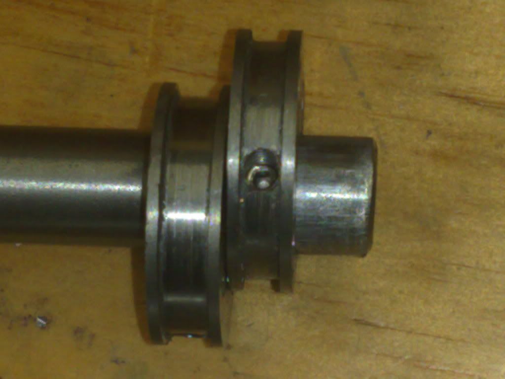
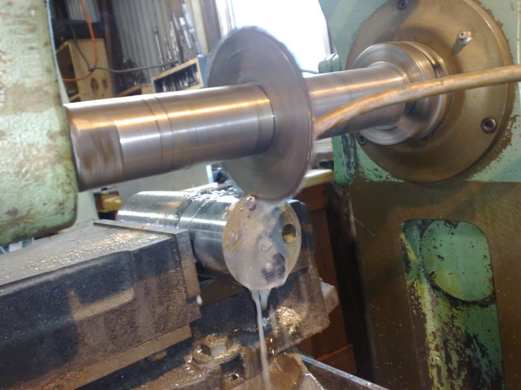
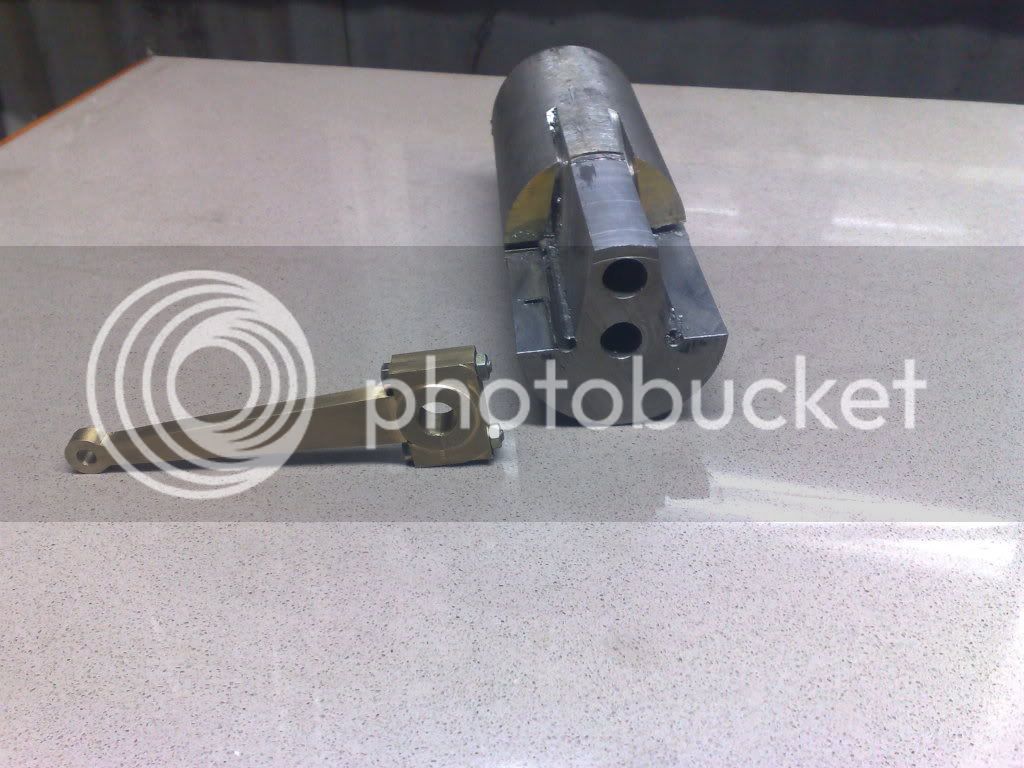
I am making the crank in two parts with a joiner in the centre. This was decided when I wasnt sure whether to use the water pump which Edgar T describes as possibly necessary for his design. This requires an eccentric sheave much the same as those for the valve gear mounted at the centre of the crank. If my crank is one piece it must be added now. If two piece I can add it later if necessary.
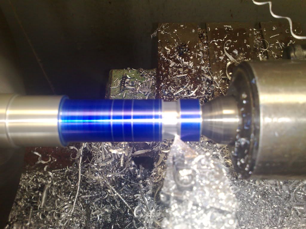
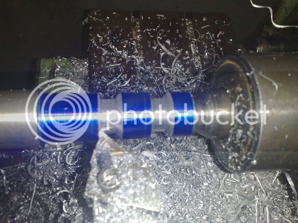
Therefore I need a joiner. I am also making the shaft that mounts the paddle wheels as as seperate units and these will run on bearing blocks mounted in the hull. These joiners will allow shock reduction (not necessary) but more importantly are flexible and will allow misalignment if I happen to build some in unwittingly.
You can see how these will look once done. These will be mounted to a one piece shaft as seen here, some release agent will be used to coat the shaft and then RTV silicone injected into the gaps and smoothed out. Once set this will supply a flexible one piece joiner.
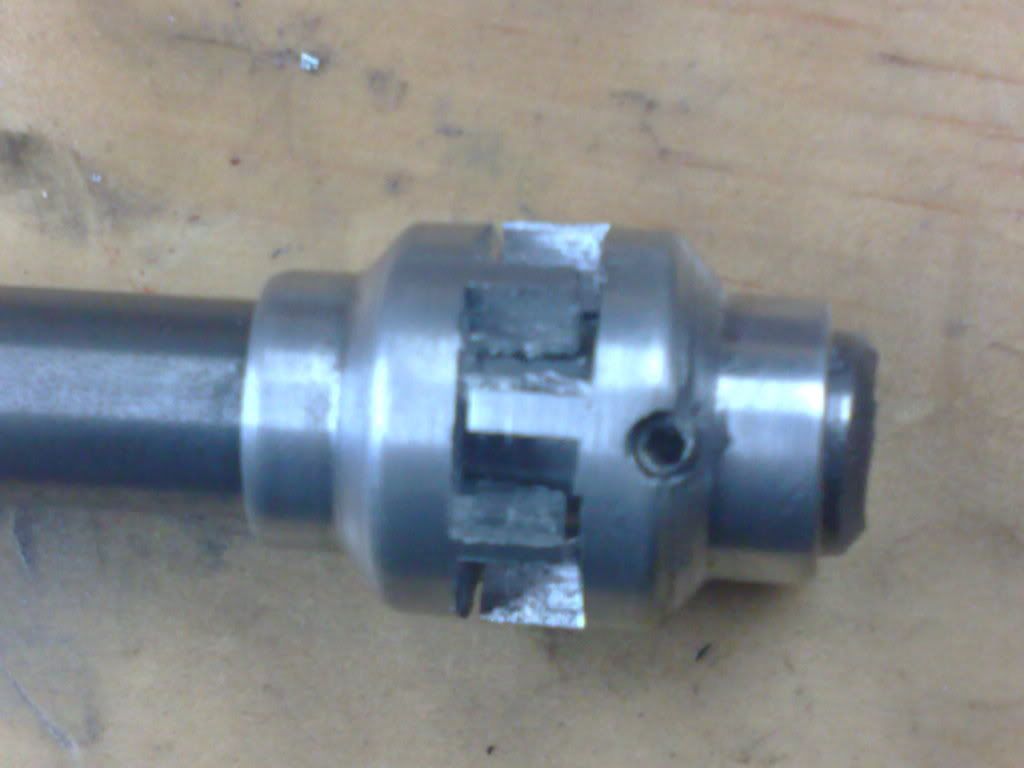
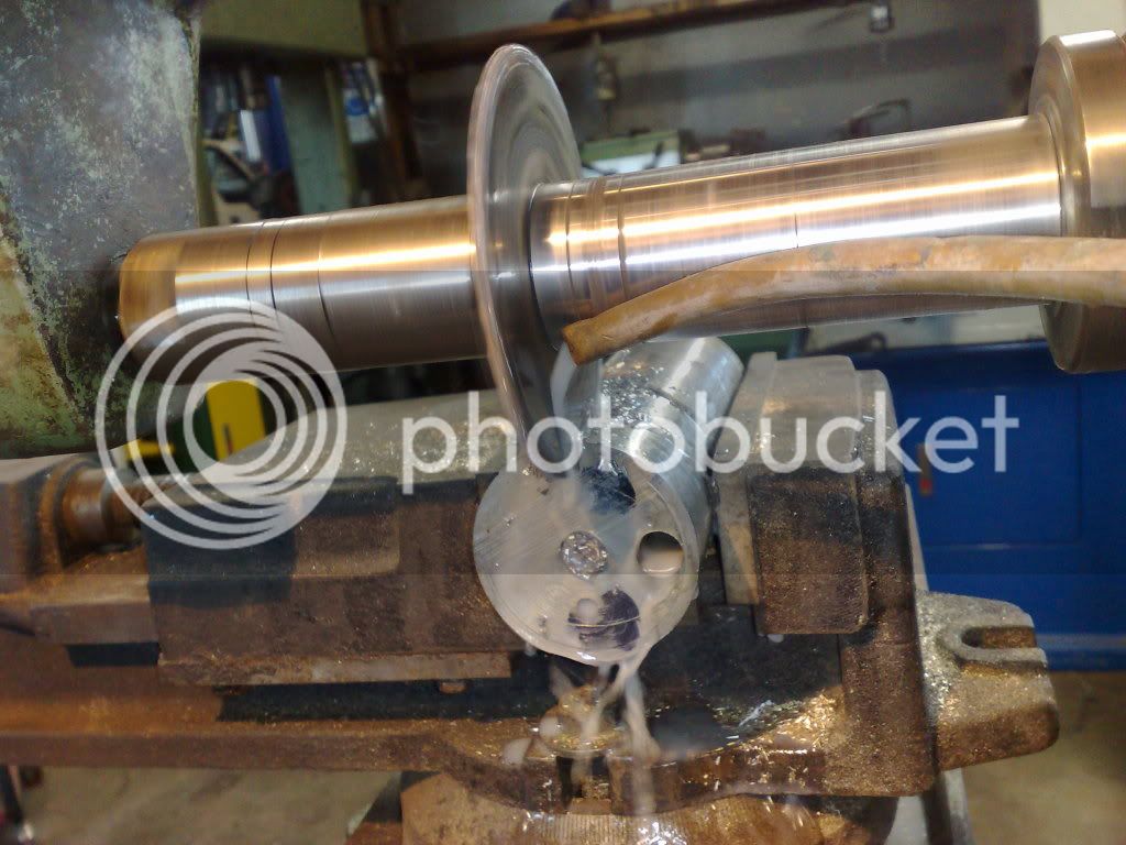
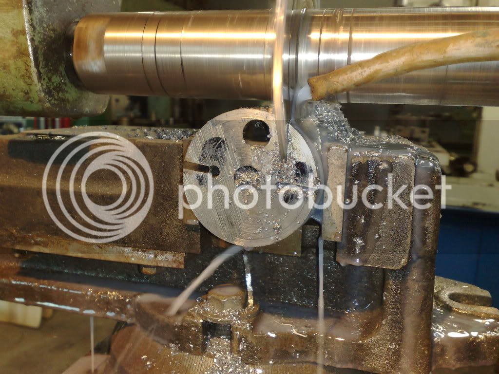
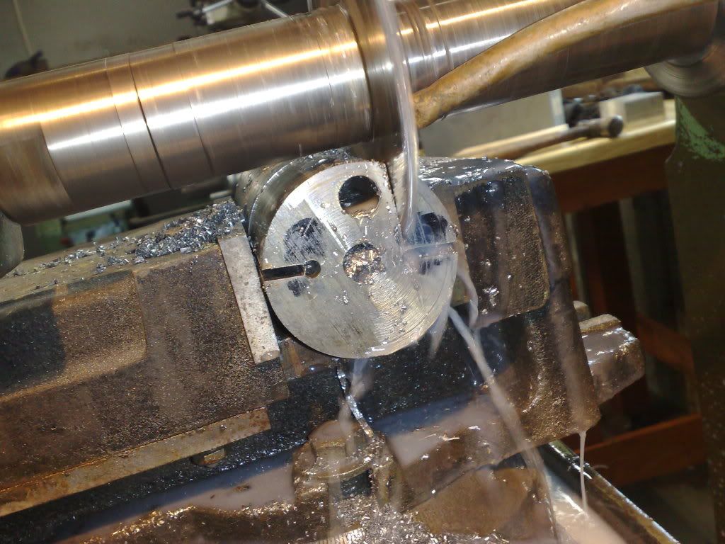
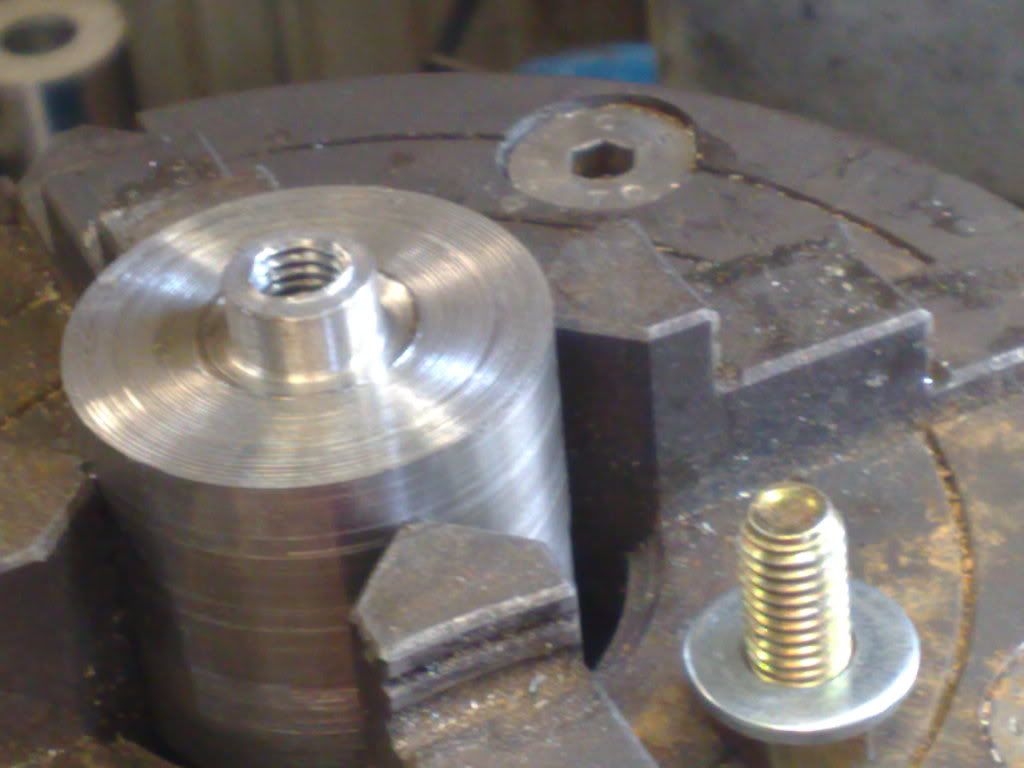
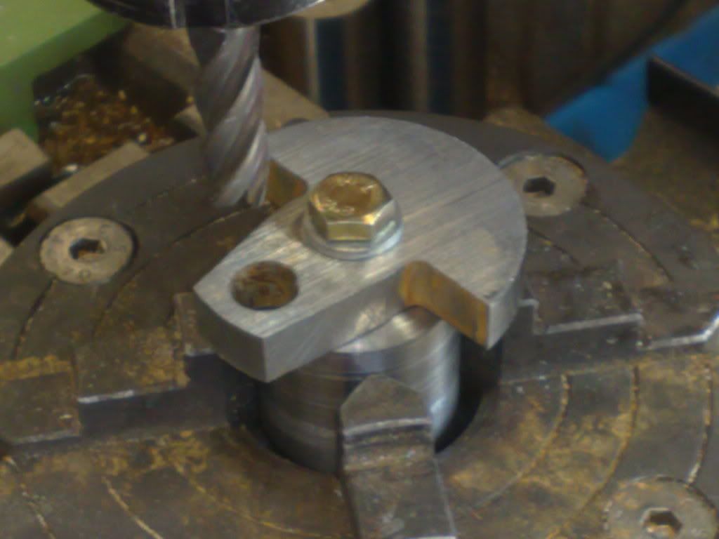
I had the RT mounted on the mill and the 4 jaw on it. A shaft is centred in this and the aluminium blanks are tapped with grub screws and mounted on this shaft. A 3mm end mill used to machine most of the material away to leave 4 'blades' which fit into corresponding blades on the mating piece.
I was going to be moving onto the rods which mount on the sheaves (eccentrics) but decided to stray... hence the joiners today.
Until next time... cheers all....
Robt T
I didnt take pics but the first eccentric took 45 mins (make tool etc) and the rest took only 10 mins each to finish.
This required setting the eccentric to its required orientation, mill a small flat at 4mm, then drill to 3.2mm and the tap in the holder to 4mm by 0.75mm pitch.
I am making the crank in two parts with a joiner in the centre. This was decided when I wasnt sure whether to use the water pump which Edgar T describes as possibly necessary for his design. This requires an eccentric sheave much the same as those for the valve gear mounted at the centre of the crank. If my crank is one piece it must be added now. If two piece I can add it later if necessary.
Therefore I need a joiner. I am also making the shaft that mounts the paddle wheels as as seperate units and these will run on bearing blocks mounted in the hull. These joiners will allow shock reduction (not necessary) but more importantly are flexible and will allow misalignment if I happen to build some in unwittingly.
You can see how these will look once done. These will be mounted to a one piece shaft as seen here, some release agent will be used to coat the shaft and then RTV silicone injected into the gaps and smoothed out. Once set this will supply a flexible one piece joiner.
I had the RT mounted on the mill and the 4 jaw on it. A shaft is centred in this and the aluminium blanks are tapped with grub screws and mounted on this shaft. A 3mm end mill used to machine most of the material away to leave 4 'blades' which fit into corresponding blades on the mating piece.
I was going to be moving onto the rods which mount on the sheaves (eccentrics) but decided to stray... hence the joiners today.
Until next time... cheers all....
Robt T
No, Artie, really............. Like a stubbed toe. :big: :big:
I really do like how you did that shock coupling. I have one of the small Stuart centrifugal water pumps almost finished and have been wondering how I would go about connecting it to a drive source. Now that I see what you are doing, the rubber hose idea doesn't appeal at all. Thanks for the idea.
BC1
Jim
Similar threads
- Replies
- 19
- Views
- 2K
- Replies
- 115
- Views
- 34K
- Replies
- 14
- Views
- 8K