Building the pump--

Home Model Engine Machinist Forum

Help Support Home Model Engine Machinist Forum:

This site may earn a commission from merchant affiliate links, including eBay, Amazon, and others.

Brian Rupnow

Design Engineer
Project of the Month Winner
Joined
May 23, 2008
Messages
14,991
Reaction score
8,285
Location
Barrie, Ontario, Canada
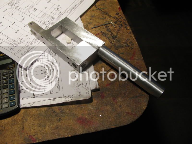
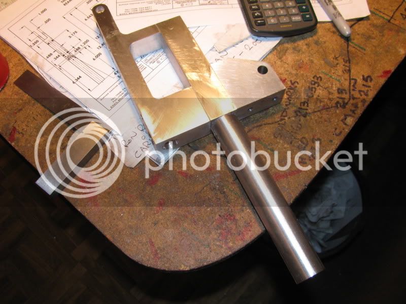
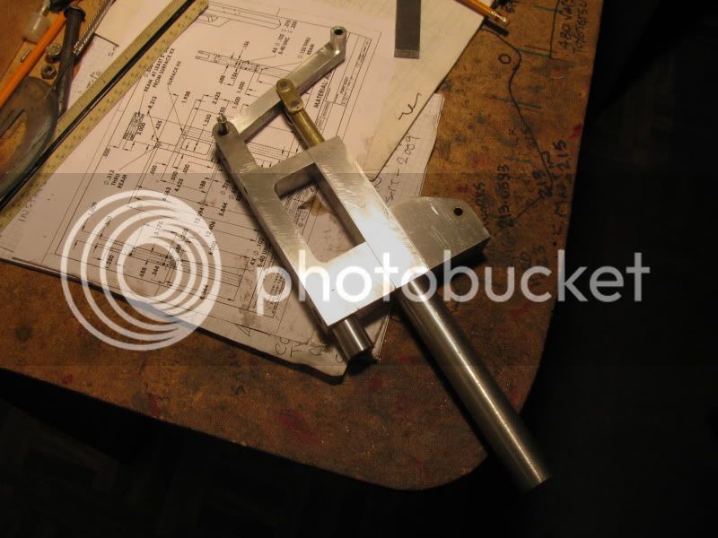
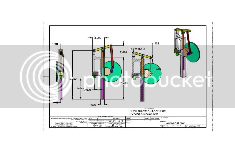
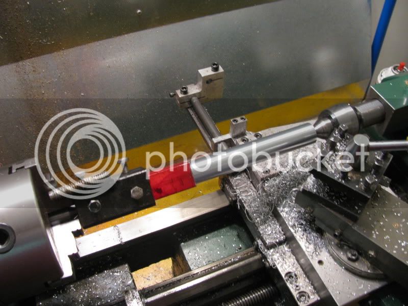
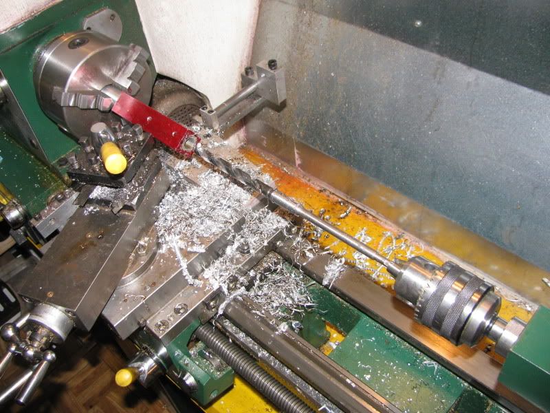
I have decided to go ahead and build the pump, http://www.homemodelenginemachinist.com/index.php?topic=6056.0 as its a slow Sunday and all of the major hot-rod (my OTHER hobby) events are over for this summer. As I started hunting through my "stash" of aluminum, the first thing to become apparent was that I don't have any 3" x 1" aluminum flat bar.---Thats okay--we're resourcefull---Make it out of two peices bolted together!! I have dismantled the "Varying load machine" and scavenged a peice of 1" square aluminum bar from it. The next thing to show up is that the maximum diameter of stock that will fit though the hole in my 4 jaw chuck is only 1 1/8", and a 1" square bar is 1.41" across the corners!! How the heck can I drill a 1/2" hole full length of a 10 5/8" long part. (Its too tall to fit in the milling machine, along with a chuck and 1/2" drill).---Like I said, "resourcefull is my middle name"---I'll turn the bottom half to 1" diameter between centers so I can grip it in my 3 jaw chuck to drill it. Are you with me so far???---I put a dead center in the 3 jaw, put a live center in the tailstock, then realize that I have no lathe dog big enough to fit over a 1" square bar.---Out to my scrap steel pile, find a peice of 1 1/2" square tubing with a 1/8" wall, weld a 1/2" peice of threaded rod to it for a "tail" that fits between the chuck jaws, drill and tap two 1/4"-20 holes on two adjacent sides of it to locate it on the square bar, and I'm off to the races!!!
ASSEMBLYOFPUMP.jpg

step-1002.jpg
 
Hi Brian.
I like your project. And I like your "middle" name :big: Thm:
CS
 
Yeah, I looked at that long hole and said to my self,"self how are you going to drill a hole that long without the bit wandering out the side of the material?" Plus get a bit that long. :shrug: :shrug: :shrug:

Ron
 
Only the top 5" of through hole is critical. That top 5" gets drilled and reamed in a conventional manner. The rest of the hole is simply clearance for the foot valve to be loctited into---it gets drilled with a 7/16" drill in an extension holder. then the part is set up in my bench vise and drilled from the other end with a 1/2" drill bit in my hand held electric drill. If the 7/16" hole wandered off center a bit, I don't realy care---it won't affect the operation of the pump.
step-2001-1.jpg


Oh I see, so simple once you see it.. :Doh: :Doh: :Doh:

Ron
 
Well Sir!!! It worked, and it worked very well indeed. I don't know as I would suggest this method for drilling rifle barrels, but for what I just did it works great. So---The first part is finished except for tapping a bunch of #5-40 holes and one reamed 1/8" cross hole for the foot valve ball retainer.----Note---It was sheer good luck, not good management that the part was only 10 5/8" long. If it had been any longer, I couldn't have got all the way though it, even with my drill extension. Sometimes ya get lucky!!!
 
After a few minor design changes to accomodate the materials I had "at hand" the pump body is completed. A lot of machining in it, but it was the most complex part that had to be made.
PUMPBODYFINISHED001.jpg
 
Good start Brian, although (Wisdom-in-hindsight is my middle name) I'd have gone about it a bit different. I would have made the top block (5'? long) and inserted a round full length tube in that. Long live Loctite!
 
This afternoon I made the bearing which supports the eccentric shaft. Of course, its not quite like the drawing.---I figured out just before making the part that it would be really nice if I had some way to mount this pump when its finished!!! So--I tweaked the bearing enough to give me a flat mounting surface on the underside. Not to worry--I will update the drawing. Tel, of course you are right. I too suffer from "Perfect hindsight syndrome". However in this case, it works well with the Rupnow austerity program (Meaning, Brian hasn't had a paying contract for almost 4 months), so we work with what we have.--No extra money to buy aluminum tubing.
PUMPBODYWITHBEARING001.jpg
 
Damn---I just had an epiphany as I sat here looking at this thing. The body disn't have to be so long. Since the foot valve tube is hollow to let the water up through it, it could have extended as far below the body as I wanted it to. It doesn't HAVE TO end flush with the bottom of the pump body as I have designed it. Oh well, every FIRST DESIGN is a prototype!!! As Tel pointed out "Hindsight"!!!.
 
Brain, here I am again, copy and paste, line this one up for a good winter project, neat one you have there, thanks again for being so kind to share, love the pics also of how it is done, thanks so much, Lathe Nut
 
Today I got the pump nozzle made and installed, as well as the plunger and the overhead arm that operates the plunger, along with the link that connects the overhead arm to the plunger. The plunger operates very smoothly with a little oil on it, and I'm sure that with some running it will get even smoother. It seems to be creating good "suction" when I operate the pump lever by hand, but of course I have to add the valves before I can really tell how well it will pump.
PLUNGERINSTALLED001.jpg
 
This morning I got enough peices fabricated and assembled to give things a trial run. I may use a different steam engine to run the finished pump, but I already had a nice gear reduction set-up put together for the doodlebug, so thats the engine that got used, for try out purposes. I still have a few things left to build to finish the pump itself, and mounting brackets, etcetera, but at least I now know it "Goes round and round and up and down!!!!"----Brian
 
I have a stash of big ball bearings that some kind soul gave me a few years ago. I have never found a use for them, so I sacrificed one today and collected enough 3/8" balls to build a whole army of pumps!! They're not stainless, but thats okay, as this pump will probably be used to pump a light oil when its demonstrated.
bearings003.jpg
 
I won't make the obvious comment about hanging on to our balls. ;)
 
tel said:
I won't make the obvious comment about hanging on to our balls. ;)
Better us than having somebody else do it----The IRD (Internal Revenue Department) keeps grabbing for mine---
 
Here we have a good shot of the two valves before I install them. The discharge valve is on the right, the intake foot valve is on the left.--(The intake foot valve is a "mock-up" for photographic purposes only.--I took a picture of the actual one, installed it in the pump, then found out the picture I took was too blurry to post!!!)
VALVES003.jpg
 
AND HERE WE ARE, PUMPING OIL!!! Now I have to figure out how to run this thing with my twin horizontal engine, make proper bracketry, and change the gear ratios a bit to let the pump run a tad faster while the engine runs a bit slower.
 

Latest posts

Back
Top