Building one of Rudy's steamers

Home Model Engine Machinist Forum

Help Support Home Model Engine Machinist Forum:

This site may earn a commission from merchant affiliate links, including eBay, Amazon, and others.
Hi Deanofid - Thanks for all that information on your lathe. It was very interesting. I still say that some of the older machinery was a lot simpler to use and just as effective (accurate). Like they say, the machine is only as good as the person running it! - Billmc
 
Bill Mc said:
Like they say, the machine is only as good as the person running it! - Billmc

Oh dear. I am in big trouble then...

:big:
 
Thanks again, Zee.
Mike, I just look at it this way. These machines were made for a man to run. Just like with anything else, practice helps.

Bill, you're welcome! Most older machines were made to last, and to do a good job over their life time. Some were made to a lesser standard, though. The little Craftsman AA lathes are a really light machine. Only about 70 lbs for a machine with a 6" swing, and the spindle in them is itsy bitsy. Something like .550 OD. They can do pretty good work, but keeping them in trim is essential to your project at hand.


Well, I just had to get the fly wheels finished up, even though it seems like I've been working on them a long time.


88.jpg


Here, the soldering job has been done on one of the fly wheels. Same solder as I used for the crankshaft.
After things had cooled off a bit, I went to wash the flux off my hands, and took the fly wheels along for a scrub
with a toothbrush and hot soapy water.


89.jpg


Then each wheel is mounted up on a face plate for truing. The spokes are blocked up with square steel pieces,
since the hub that sticks out on the other side won't let them sit flat. Then they are just snugged a bit with the
hold down nuts so the piece can be centered.

I had drilled center holes in one side of each hub just for this purpose when I made them. The dead center in the
tail stock is run into the center hole and the piece can be positioned. Then the hold downs are tightened.


90.jpg


Then the wide rim surface and it's edge are trued up all nice and stuff..


91.jpg


The center hole is then drilled through and reamed to fit the crankshaft. After it's reamed, the piece is flipped over
onto the other side and the other edge of the rim is trued.
It's done similar to the first side, except to center it this time, a rod the size of the hub bore is put in the tail stock
drill chuck to center it.


92.jpg


Those things are done! Here's a fit up shot, with some bits I cut up for tomorrow's work, along with today's
offering to the god of steel. My last good Starret blade. Oh well, it's been on the saw for about a year.


93.jpg


'Til next time, then!

Dean
 
Very nice work and a great thread. Good pictures, too! Love following these builds.

Chuck
 
Thanks again, Arnold!
And thank you, Chuck, for having a look-see.

I appreciate everyone's comments.

Dean
 
Hi all;

Just a bunch of little bits today, mostly for the crosshead guide.


94.jpg


I spent a little time milling the ends off the crosshead guide base and spacers to get them to length and
square them up, then settled into drilling. I used milling machine coordinates to locate each hole.


95.jpg


There were a couple of the pieces that I didn't have as stock metal, so had to mill them to proper thickness.
On this piece, the closest I had was 5/16" x 1/4", but it needed to be 5/16" x 1/16". Cut, cut, cut!


96.jpg


After getting them down to within a few thou of finished thickness, I ran a fly cutter over them.


97.jpg


These are the finished pieces. The two stubby pieces at the top of the picture are for the cylinder
mount. The smallest one is for the eccentric shaft guide. The rest are crosshead bits.


98.jpg


The next thing to do was to make the crosshead studs. They need to be threaded for 2-56 each end, and I
don't have any round stock that's the right size for that, so I turned down a few inches of 3/32" drill rod and
threaded the ends.


99.jpg


One down, five to go.


100.jpg


When they're all made up, they tread into the base.


101.jpg


Here are the bits all assembled into the crosshead guide. I made the nuts too, but forgot to take pictures of that.
They don't represent much of a story, really. Get the size hex rod you need, drill it and tap it for the threads you
want, and part off whatever looks like a nut. If you need six, do it six times.


102.jpg


A little more done. Quite a bit to go.

Dean
 
Nice work Dean. Very consistent. Wish I could say the same about your choice in M&Ms.

Seriously though...nice tip for some of us..."milled down to a few thou and then switched to a flycutter". Helpful.
 
Zee, thanks again. I'm sorry for subjecting you to M&M's that are not tan colored. I'm just a poor boy, and can only afford the red, yellow, and green types. I checked on ebay for tan M&M's, but they are way out of my price range!

Kvom, thanks! Cutting the heads off some screws would have saved some time. I don't have any 2-56 screws that long, though.

This project is kind of on hold for a couple days. I bought a new (old) lathe, and am preoccupied getting it cleaned up and fit for duty. It's hard to let a lathe sit in pieces in boxes on the floor while making little parts for the engine. I get distracted!

Dean
 
Dean,

As always your work is magnificent. I learn something almost every time I check out your progress!

So, a new (old) lathe... You gonna tell us what it is? Oh, and pics or it doesn't exist! ;)
 
Thanks Mike!

"So, a new (old) lathe... You gonna tell us what it is? Oh, and pics or it doesn't exist!"

For your doubts, all you get is a pic of the spindle tear down. You get to guess. Lots of folks here will recognize it.

It's coming to me in dribs 'n drabs. The previous owner sent it in five separate boxes. Still waiting on a couple of them.

spindle.jpg


Dean
 
Hi Dean: Those 2-56 studs you made look nice. I have a favorite very old time hardware store where I can usually get old stuff. The nice people who work there tore the screw department apart looking for 2-56 screws and the longest they had was 3/4 of an inch. I did manage to get some nuts. So I plan on turning some stock down and making mine two. Good luck with your lathe project. I am always doing two things at one time to. Jack
 
Thanks Jack! I appreciate your comments, especially since we are building twins.
I've never been able to find any kind of 2-56 screws longer than 1/2" where I live. It's a small town, (3500), and some little bits are not to be had, (but if you want something for a John Deere, you're in luck!). I make most any fastener I need that is smaller than 4-40, out of necessity. I kind of like making my own cap screw nuts in the smaller sizes, simply because most store bought items look oversized across the flats.


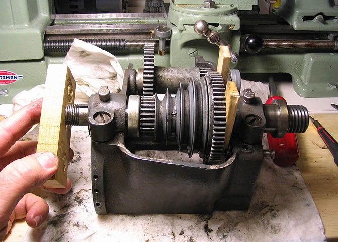
Got a little done today. I'm not a fast builder. Been occupied with the new/old lathe, and plowing this
morning's eight inches of snow off my 1/2 mile long driveway. Excuses, excuses.


103.jpg


This will be the big end of the connecting rod. Remember that piece of 3/4" square that was made
from a piece of round stock earlier? This is some more of it, here. It will be .625" square when I
get done with it. Hack-sawed a little piece of it off and in the picture it's being cleaned up with the fly
cutter.


104.jpg


Once the piece is brought to its proper thickness, it's put on end to take one side down to finished
size. It needs to be square, and in this shot I'm checking it with a small machinists square and a
flashlight. The flashlight helps you see the edge of the piece against the square, and by the light
that comes through, you can see if it's square or not.


105.jpg


I need to drill the cross holes in the piece next. Above, a cigarette paper is being used to find the edge
of the work piece. I've known a number of ol' machinists that use this method, even though an edge
finder might be handy, and I use it often myself.

For those who may not be familiar with it, you put your piece of paper against the work piece and run
your tool up near it, then crank the slide over slowly while pulling the paper back until you feel the tool
start to barely pinch the paper. You do this with the machine turned off, by the way. When the paper
starts to get stuck between the tool and work piece, you're there, within the thickness of the paper.
These particular papers, (Top brand) dial at .001" thick. If you buy a different type for rolling up your la
bambas, they might be thicker..

Some machinists do this trick with the machine running, and when the tool snatches the paper from
between their fingers, they know it's good. For my part, I'm pretty attached to my fingers, and would
rather do it with the machine turned off.


106.jpg


The holes are drilled through for a 2-56 tap.
The blue line is an index mark so I keep the pieces matched up after it is cut in half.


107.jpg


Then the piece is cut in half with a hack saw. I would have used a slitting saw, but I seem to have
misplaced the arbor that fits my milling machine. At this point, the piece is to the proper width, but
was left long to allow for the saw cut.


108.jpg


After the two pieces are cleaned up from the hack saw job, and brought to the correct width on the mill
at the same time, the holes in one piece are tapped 2-56. Tapping small holes in brass is almost fun.
There's so little chance for trauma or drama, like when using small taps in hard metal.


109.jpg


The bottom half is on the right, and it has the tapped holes. The top part, on the left, has had its two
holes drilled out to #43 clearance holes for the two little cap screws.


110.jpg


After putting the two pieces back together using the cap screws, the piece was center drilled at the
location of centerline for the bore for the crank pin. At that point, I realized I didn't have a 5/16 reamer
to finish the job in the mill, so while it was still in the mill vise I drilled a small hole clear through. Then to
the lathe I go.
The piece was mounted using a piece of tool steel between it and the face of the chuck to keep it
square, then the tool steel was removed. Note the pieces of paper wrapped around the brass piece. I
don't want marks in these soft brass bits. I centered it by eye close as I could, then dialed it in with the
old Gem held in the tool post. I like this type of DTI, and prefer them to my other DTI's. They're pretty
darn reliable, the point is easy to reposition, and though they only operate in one direction at a time,
you can switch directions with a flick of the lever on the (other) side of the body.


111.jpg


Then the piece is bored for .312" plus a smidge, for a close running fit on the crank pin.
A "smidge", by the way, is different for different sizes of running fits. Machinery Handbook has a section
on them, I believe.


112.jpg


The last step I'll show is cutting the relief on the sides. Simple turning job. I used a 5/16 piece of drill
bit as an arbor, with a couple of snips of paper squeezed between the work piece and the arbor to
make it tight. If the pieces of paper aren't used, the piece will simply spin on the arbor, since it is the
same size as the crank pin, and is a running fit in the work piece. An oil cup has to be made for this, but
I won't show it here since I already showed the same things being made for the main bearings earlier in
this thread.


113.jpg


That's it for today. I know it's a lot of pictures for such a little thing, but I figured a few folks might
want to see it.

'Til the next part, thanks for having a look.

Dean


Great work, Dean. I learn a lot by watching all of the detailed threads and this one is a good one. Thanks!
 
Deanofid said:
Tapping small holes in brass is almost fun. There's so little chance for trauma or drama, like when using small taps in hard metal.

I know it's a lot of pictures for such a little thing, but I figured a few folks might
want to see it.

That 'little chance' is a function of experience. Or change 'trauma' to 'success' and you will have described me. I have a pic somewhere on my own thread showing a piece of brass with a broken tap. ;D

I'm a 'few folks'! Thanks for the detailed descriptions and pics. Really good stuff.
 
Dean, your blow-by-blow commentary is terrific Thm: as are the photos that accompany the same. The end results, well, they are just plain magnificent :eek:. I do appreciate all of your time in documenting what some would call mundane and boring steps, but it is easy to take these things for granted and refreshing to see perhaps better methods of execution than one is used to. BRAVO! The flywheels still have me a bit turned around but I just need to settle down and concentrate a bit more to fully grasp the sequence of events :noidea:. Thank you for sharing this adventure with us. *discussion*

BC1
Jim
 
Paul, thank you! I appreciate you checking out the build. If you see something you can use, all the better.

Jim, thank you very much! I'm humbled by such kind comments. Very much appreciated!

Zee, thanks again. Always glad to see your comments!
I know taps are sometimes a problem, especially when a person is still gaining experience. There is a very subjective aspect to it, when it comes to the "feel" of things when turning the tap, but there are a few things to do that are not technique dependent that will increase your chances of success.

Start the tap straight in the hole, and keep it straight. Starting a tap just a little crooked is probably the biggest cause of broken taps. Make yourself a tapping block and use it always.

Use lubrication if it's called for. Not really needed in brass, but aluminum benefits from it because it has a tendency to gum up the tap flutes. Steel is just plain hard, and lube will help with cutting, breaking the chip, and to keep chips from jamming in the flutes. With machinable cast iron, I don't usually use a lube.

Don't put any side load on the tap. The tapping block helps here. You can break a tap with a side load even when going into a previously tapped hole. This is connected to keeping the tap straight, but even if you keep it going straight, if you put pressure on the side of the tap, it will break, especially in the smaller sizes. Using a guide, like the spindle of a drill press will help.

Break the chip often, and back out the tap completely and clean out the hole when tapping blind holes.


Still pecking away at the engine, a little at a time.
Finished up the con rod today. Here are some more pics and natter.

114.jpg


This piece will be the small end of the rod, that connects to the slipper on the cross head. It needs three holes drilled in it, and two of them tapped. The smallest one needed is 2-56, and I'm in the habit
of tapping the smallest holes that are needed in a piece first, if it fits in with how the piece has to be
made. I don't break a tap too often, but it does happen, and there's no way around it. If you make
stuff, you'll break a tap now and then. By doing the smallest threaded holes first, if one should break,
you haven't got so much time invested in the piece if it ends up as scrap.


115.jpg


Next the piece is turned on its side and the bore for the slipper shaft is reamed. The end was also drilled
and tapped for the shaft that connects the two ends of the con rod. In Rudy's prints, he shows it being
soldered into this piece, but I want to thread it, as it's easier to time the two ends of the rod when it's
done.


116.jpg


I turned up the rod that goes into the ends of the two bearing ends. No pictures of that little job. Just
turned a 1/8" diameter on one end and thread the other end to match the thread in the rod's small end.

In the picture above, I'm checking to see if things are square. For small items like this you can get a
pretty good idea of how things sit in relation to each other by eyeballing it against a flat surface, like the
bed of the lathe. It's not precise, but you would be surprised how close your eye will judge things when
it has a reference.


117.jpg


I've made round ends on things like clevis ends or rod end eyes using this method (above) for many
years, but had always used a small end mill to do it. Marv mentioned in a post that he used a carbide
bur instead of an end mill, and it's a very good suggestion. The bur has so many cutting edges that it
doesn't seem to want to grab, as an end mill sometimes will. Thanks Marv, (Merv?).


118.jpg


So, these are the parts that need to go together. The bottom piece is the flange that holds the rod to
the larger bearing. It's not quite finished yet.


119.jpg


Here, the flat piece has been soldered to the rod, using the same solder I used for the fly wheels, (silver
bearing soft solder).


120.jpg


The rod is put in a collet in the lathe and then the end of the flat mounting piece is turned down. I made
it from 1/8" thick material, but it needs to be 1/16" thick when finished. This step also assures that the
flat end of the piece is perfectly square to the rod. (Obviously the solder held up well.)


121.jpg


The last machining step on the flat piece is to drill the mounting holes to attach it to the large end
bearing. I used two machinist clamps to hold it together while drilling, but removed one for this picture.
This is the way Rudy did it, so I followed his example. He knew what he was doing.


122.jpg


Ka-rud! I made up some more oil cups similar to the ones made earlier in this thread for the crank
bearings. While checking for fit... Well, you can see what I did. I'm sure glad they were made of
brass. I drilled it out with a pin vise, (finger drill) and re-tapped the hole, and all was well, but it took a
while. The threads are not that delicate, but are quite small. I broke it off doing something dumb.
After cutting the thread on the work piece, and while it was still being held in the lathe, I threaded the
crank end onto it to check it. Turning the lathe pulley by hand while holding the crank end between my
fingers made a lot more torque than the little thing could stand, and it gave up the ghost.


123.jpg


Here are all the pieces except for a little bushing that goes into the small end piece.


124.jpg


And here is the completed connecting rod.

Well, the bed for my new/old lathe came today, and I have enough pieces to start putting it together,
so the steam engine will probably be on hold for the weekend.

Thanks for having a look. More steam engine stuff in a couple of days.

Dean


Hi Dean,
I very much like the style of the engineering that has gone into the connecting rod. My favorite bolted joint twixt rod and big end and the imitation shell bearing. The oilers just finish off the piece and gives it that full size effect without actually going there. Great. Keep it up.
Cheers,
Brian
 
Back
Top