Brian's Donkey Engine

Home Model Engine Machinist Forum

Help Support Home Model Engine Machinist Forum:

This site may earn a commission from merchant affiliate links, including eBay, Amazon, and others.
Yes the PM research ones are good, I've bought several of the un machined trees of castings, use them on this, the nutted unions you will have to make yourself. I used 40tpi ME threads.

PICT0341.jpg
 
Brian Rupnow said:
Who knows if these Donkey type engines had cladding on the boiler? Any videos I have ever seen of the real ones just show a smoke blackened boiler, I've never seen one with cladding.---Brian

Brian - The Donkeys I climbed all over in Oregon primarily at Camp 18 http://www.camp18restaurant.com/loggingmuseum.html did not have any cladding on them. I do not remember seeing any with any cladding but that doesn't mean there weren't some built that did. My guess is since these were initially used in the logging industry, fuel was not in short supply and therefore heat loss from the boiler skin was not important.

I would think when they were later placed into steam shovels and drag lines where they burned coal and oil that they were placed into cabins and perhaps had cladding added at that time not only to conserve the heat but to protect the operators. If you would like I could contact Marv Johnson and ask him.

Harold


Thanks Harold---Thats what I thought. Here is steamchest #1 well on its way to "becoming" both in the milling machine and trial fitted to the cylinder.
donkeysteamchest001.jpg

donkeysteamchest005.jpg
 
This evenings offering is a gaggle of cylinder end caps. The diameters come out fairly good. The finished thickness of the end caps though, thats another story. According to the drawing they are supposed to all be 0.197" thick. I have one at 0.208, one at 0.203, one at 0.216,and one at 0.178!!!! It is plain that my methodology for turning steps to a finite length could use a whole lot of improvement!!! This is not a particularly critical measurement, and its one of those things where if its not visibly different, it doesn't really matter. The one undersized one is a rod end cap, and I'll have to thin out the other rod end cap to match it, but at least no one will notice and it isn't the kind of thing that demands remaking a part. The chatter marks you see are a direct result of machining with my cut-off tool, which is the only damn thing I have for plunging into round stock and ending up with a square corner. Again though, those chatter marks will be hidden inside the crosshead tube. Its a bit like that old army song "But my socks don't show, and the Sarge don't know, about my dirty undies!!"---I continuously strive to make more uniform and better toleranced parts, as I learn this machining game. I have improved in a lot of areas, not so much in others. I WILL try harder!
endcaps-1001.jpg
 
One cylinder is almost complete. I have to order a box of shorter bolts tomorrow, but at least all the holes line up. (Which is always a great relief to me)!!!--My real job is interfering with my play job, so I didn't get much done today.
onecylinderdone001.jpg
 
Hello Brian,

Great job as always. I always enjoy following your design progression and your builds.

You mentioned that your parting tool is the only way that you can machine a square shoulder. Do you only use carbide insert turning tools or do you use your own hand ground and honed HSS tool bits?

The best way to achieve a square shoulder is with a combination of turning and facing out (or in to your finished diameter) with the cross slide, using the lathe's built-in 90 degree angle. Of course, this would leave the radius of your tool bit in the corner, which is completely under your control with a HSS tool bit as it is honed on after grinding.

Dinner is ready, must go.

Keep up the great work.

Kind regards,
Mike
 
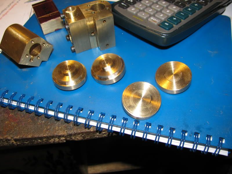
Mike---When I made those four end caps, I did it by turning the o.d. on a single piece of brass to the largest diameter, then parting them off one at a time. As you can see, there are a number of "steps" in each end cap, and the only way to really accomplish what I did is to plunge blind and depend on the dials for diameter, and also to depend on the dials for travel along the bed. The parts are so short that once cut from the main piece of brass its damn near impossible to set them up individually in the chuck for more work and have them "run true", so I like to get all the turning, facing, drilling, reaming, etcetera all done while the pieces are still attached to the main blank in the chuck. I know I could build a chuck spider or a "purposed collet", but the way I did it works---its just not horribly accurate. ---And Oh yes, I grind my own HSS cutters.
 
Time to invest in some soft jaws me thinks, would easily hold those cylinder covers true so the second side could be machined eliminating those chatter marks. Or just make up a simple split bush to hold them with that has a step to register against the front of the chuck jaws and a back to it to keep the part true.

J
 
Split chucks get my vote - so simple to make, and once you have one for a particular job you could literally face off hundreds of pieces to identical thicknesses. I have quite a stash of 'em now - if they won't fit the next job that comes along they are very easy to modify.
 
Here is a cylinder cover being held in a split chuck


and here is the split chuck


and here is the cover

 
Thats the thing Tel, also very handy for holding gears with tooth counts that are not divisible by 3.

J
 
I'm old but I do have the odd trick up my sleeve.. This is how I trued the end caps up in a secondary operation. I found a short piece of black iron pipe and couneterbored the end for a light press fit of the disc o.d. The c'bore was shallow enough the half the face thickness stuck out past the end of the pipe. This let me "true" all the thicknesses and adjust any diameters I needed to adjust.
dedicatedchuck001.jpg
 
Now if you had shortened that up a bit, cut a chucking spigot on the other end, and ran a saw cut through the side, you would have a split chuck. The spigot locates against the chuck jaws, ensuring repeatable location, then you lock the X axis feed and face in with the Y for however many pieces you want to do.

Oh, and mark the position of the no.1 jaw, for that bit extra repeatability.
 
Progress was made in leaps and bounds today!!! If the Lords willing and the creek don't rise, I might actually get to make a piston and rod and try one of these cylinders out tomorrow. I REALLY hope they perform as expected.--and yes, those registers with the so ugly chatter marks on them are hidden----they are covered by the crosshead guide tube.
pairofcylinders001.jpg
 
Here we are, right into the messy end of the business!!! Last night before going to bed I made up the 3/16" diameter cold rolled piston rods and threaded both ends. Then I turned the cylinders to 9/16" diameter and drilled and tapped them in the lathe, then parted them off from a piece of 3/4" aluminum round rod. I coated the threaded end of the piston rod with 638 Loctite and screwed the pistons onto the rods as far as they would go---even gripped them lightly with my pliers and made sure they were tight against the end of the tread. These sat up overnite under a 100 watt bulb, and this morning the Loctite was fully cured. Then each piston and rod assembly went back into the lathe, the rod in the chuck, and the piston was Oh so carefully turned to 0.500 dia. This is a very delicate turning operation. 0.001 too much left on the diameter,and they won't go into the cylinder bores. -------.001 too much taken of the piston and the damn things fall into the bores. What you see in the picture is the messy business of lapping. Even though the piston will (theoretically) fit into the 1/2" reamed bores, there will still be "tight spots" over the length of the piston travel that must be addressed. To do this, the piston is coaed with 600 grit lapping compound and gently worked from end to end of the cylinder. I find that what works best for me is to set the cylinder on my desk top where I can hold it firmly with one hand, while lifting and lowering the piston rod full stroke, like an old "dash churn" and revolving it about 5 degrees (finger estimate) between plunges. (Not during the plunge) I do this 50 strokes on each cylinder and piston assembly.---And note that when you have a twin like I do, once the lapping is completed, the piston is "dedicated" to the cylinder it was lapped in---don't mix them up after this step!! Next step will be to do a complete and carefull Varsol wash of the cylinders and the piston assemblys to clear out any remaining lapping compound.
lappingcylinders001.jpg
 
Now, if I but had some valve cover plates and a whole whack of gaskets we could try this thing out!! One valve is centered nicely in the housing, while the other has a bias to one side. This might cause a problem, but then it may not. There is a certain amount of "float" built into the design of this valve body, so we'll see whan I get some air on it.
valves001.jpg
 
And yes, virginia, we do recycle the offcuts. and then we even recycle the offcuts from the offcuts!!! With the cost of brass climbing to absolutely insane prices, I would even recycle the chips if I could just find a way to hold them.---Brian
offcuts001.jpg
 
Finally, by what I see is almost the end of the day, my reclaimed offcuts have magically turned into a nice set of valve cover plates.---(Resting on a much used and abused 1/4" parallel). That about does it for the physical build of the cylinders. Next up are a full set of fabricated gaskets, disassembly, reassembly, and a quiet prayer.
valvecovers001.jpg
 

Latest posts

Back
Top