Brian's Donkey Engine

Home Model Engine Machinist Forum

Help Support Home Model Engine Machinist Forum:

This site may earn a commission from merchant affiliate links, including eBay, Amazon, and others.
I have been studying Captain Jerry's clutch mechanism which he came up with for his Donkey engine build. It is indeed a clever mechanism, and there are some vitally important parts that simply don't show up or get mentioned in his posts. I have wore my "engineer detective" hat all morning, and I'm pretty sure I have sussed out how Jerry did it. I am going to post a drawing and a few solid models to show how I believe this clutch works.
DONKEYCLUTCHSHOWANDTELL.jpg


View attachment DONKEY CLUTCH SHOW AND TELL.PDF
 
These two models show the components inside the clutch. Of course that purple shaft with the round knob on it which I called an "activation pin" is in there only for "show and tell". In reality it will be a short pin operated by a hand lever to engage and disengage the clutch. There will also be a spring under that sliding hub which under normal circumstances will hold the sliding hub away from the winch so that the clutch shoes don't constantly "drag" on the inside of the winch drum. I will post more about that lever as my design progresses.
DONKEYCLUTCHSHOWANDTELL-model.jpg

DONKEYCLUTCHSHOWANDTELL-exploded.jpg
 
Brian-

Nice Solidworks stuff.
Once you learn 3D, it is hard to imagine designing anything in 2D.

Looks nice.
 
Hey, I like that clutch arrangement Brian - you're not just a pretty face, are you! (some say not even a pretty face)
 
Well there!!! Thats another 6 hours out of my life that I won't get back.----Modelling clutches. The models do look great, don't they.--Can't really take credit for the design though. Captain Jerry did a remarkable job on coming up with this clutch in his original Donkey post.--I just had to do a bit of detective work to figure out what he'd done. Thats enough for now. I'm off to my metal supplier with a barrow full of money to buy brass.
FULLASSEMBLYDONKEYWITHCLUTCH.jpg
 
And that, my friends, represents $260 of the finest Canadian dollars!!! I struggled up to the "Pay" counter with all my bits and pieces and damn near fell down dead when the clerk toted up the price. I had stopped at the bank yesterday and got out $100 thinking that would cover it. Now I know why I keep taking design contracts even though I am 65 and theoretically retired. I'm just like a junky, working to support my habit.----There---Now that I've had my little hissy fit for the day---That much money for what will probably be 2 or 3 months entertainment for me probably is justifiable.---Just makes me wish I'd been born rich instead of good looking!!!
MATERIALFORDONKEY001.jpg
 
Brian

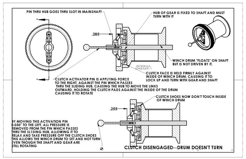
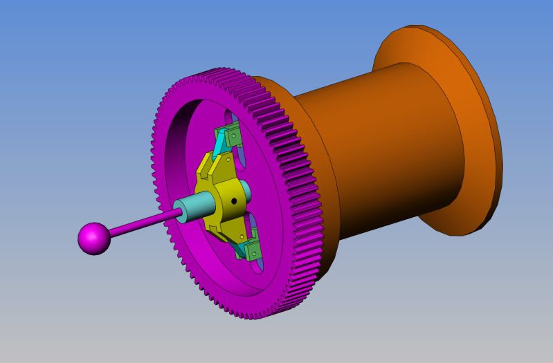
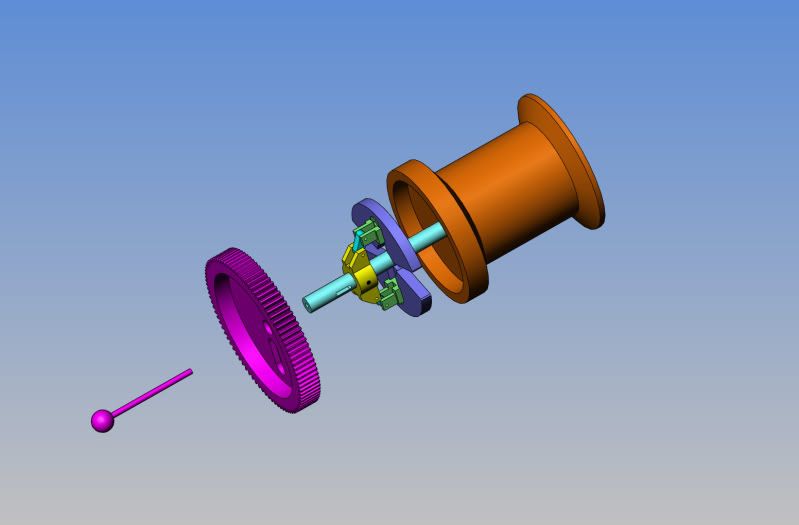
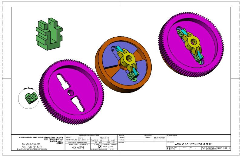
I hesitate to point this out as I don't want to seem overly critical but there are a few things that you may have missed in my design. I did not emphasize it in my post but the clutch friction plate should expand outward and not be pressed axially against the clutch drum. In the AmHoist design as shown in a photo in reply #22 of my donkey build, the slider at the outer end of the expansion link, has a flange that slides on the gear web and absorbs axial thrust. My version of that slider shown on reply #23 has a similar flange. I also found that the pivot point for the link to slider (outer end of the link) needs to be below the surface of that flange to prevent the whole thing going cockeyed. You will see that on the original as well as my version.

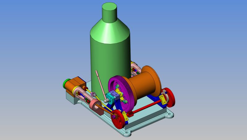
As you will find when you begin to test this winch, axial thrust will cause all sorts of problems. For example, the gear must be prevented from rubbing on the clutch drum flange and the Winch drum which is integral with the clutch/brake drum must be isolated from all axial loads. If I had a half dozen of those nifty little ball thrust bearings, I would use them on this.

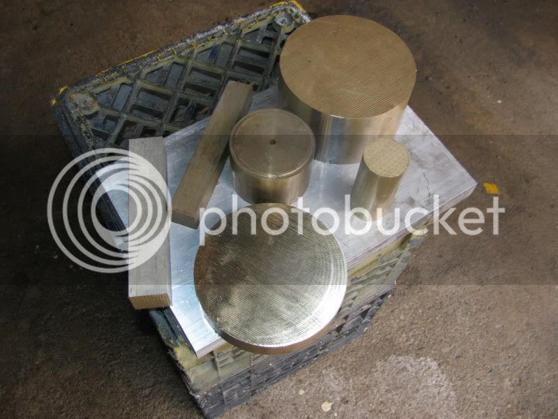
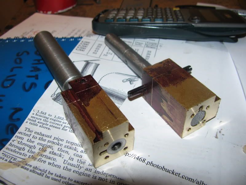
I felt that I had to mention this because that gear and clutch drum represent a sizable investment in brass, as you well know. I worked some of this stuff out in aluminum before putting tool to brass.

Jerry

 
Jerry--I see your point my friend. I have added a second flange onto the top of that green slider, so that it is fully supported on both sides of the remaining gear web. No axial forces at all will be passed on to the clutch discs. Fortunately there is a very small amount of travel in that green slider, so I was able to cut a larger access hole right next to the hub of the gear to get the slider in and slid into place.
ASSYOFCLUTCHFORGERRY.jpg
 
Brian

That's the ticket. I think you might like the action a little better if you move the pivot pin hole in the green slider down to sit between the flanges. That has two advantages. First, it prevents the slider from cocking and binding. Second, if you polish the ends of the pivot pin the sides of the slot in the gear will act as the retainer.

You are renewing my interest in this project. I have a feeling that it won't be long before I get back to it.

Jerry
 
For those of you who like to see "in process" shots, this is the way I start the cylinders. I am machining them from 1 1/4" square stock. I cut them 1/2" longer than I really need, machine the overall rectangular shape to size, and cut away any material that is parallel to the sides. Whats left get set up in the vice, checked for being "true and level" and then I drill and ream the 1/2" bores in place. (When I set them up I had a 3/8" parallel setting under them to provide drill clearance when the drill breaks thru the bottom of them). Still in the same set-up I drill the 4 holes in each one which will be tapped to hold the end caps on, drill the steam gallery that goes thru to the near side port, and mill away some material between this steam gallery and the cylinder so that steam can flow from the gallery into the cylinder when the end cap is bolted in place.
DONKEYCYL-1002.jpg
 
Now,----You were wondering why I cut the material for the cylinders 1/2" too long, weren't you. Well, I needed to make some handles for them---and the handles are absolutely not allowed to rotate in the cylinders. After I made up a couple of handles from round scrap (Turned to 1/2" dia. to fit the cylinder bores.), I cross-drilled through that extra half inch of material at the end and put a 3/16" split pin thru both peices to hold the handles in the cylinders. I stuck the handles into my lathe and took a clean-up pass across the face of each cylinder. This makes certain that the end face of the cylinder is perpendicular to the bore. I then set my vernier caliper to the cylinder length I actually want to end up with and scribed both cylinders in the area where the red layout dye is. Why did I need handles?---It will all become clear in my next post.
cylinderswithhandles003.jpg
 
And now you know what the handle was for!!! (If you followed my popcorn thread, then you have already seen this done). It works so neat!! Next thing I will do is set it back up in the lathe and part the cylinder off to the correct length.
CYLINDERPROFILING002.jpg
 
No progress today. Had to make what seemed like a terribly long drive over to western Ontario to Brussels and see a customer. It was only 360 Km round trip (225 miles) and I did get a new contract, but it was a grey dismal day and I didn't sleep much last night. I would much rather have been tucked up in my nice little machine shop finishing off Donkey cylinders instead, but I've got to do something to keep money flowing so I can keep buying tools and pay for brass!!! ::) ::). ---Brian
 
Brian is it me or have you NOT made a handed pair ??? Surely you should have a left and a right.

Or will they have the same drillings on the other end? making them interchangabel?

J
 
Jason---Shows your thinkin' lad. The cylinders are symetrical about centerline, or ambidextrous, or bisexual, or something like that!!! They aren't right and left anyways. However, the steam chests may be, depending on where the steam inlet is positioned.----Brian
 
Tonight we have a pair of finished cylinders, and a pair of "steam chests to be". Tomorrow I will finish the steam chests and maybe carve out some cylinder end caps. Of course the wisest thing would be to finish one cylinder assembly completely and see if my maiden voyage into port design works out okay---However, faint heart never won fair lady, and its easier to make two of everything as I go along.
finishedcylinders001.jpg
 
Who knows if these Donkey type engines had cladding on the boiler? Any videos I have ever seen of the real ones just show a smoke blackened boiler, I've never seen one with cladding.---Brian
 
Jeez, I'm full of questions tonight. Where does one go to get miniature brass or black iron pipe elbows? I'm thinking something that would be suitable for use on a "pipe" about 3/16" or 5mm in diameter. If I do this donkey up the way I'd like to, I want to have the steam pipes from the boiler to the cylinders to make it look authentic. As I'm setting here typing this, I'm thinking "Probably the Model railroad guys have a source for this stuff.----God knows there was enough pipe and elbows on the old steam locomotives."
 
Brian

PM Research have some nice pipe fittings in a variety of sizes.

Joe
 
Back
Top