Brian's Donkey Engine

Home Model Engine Machinist Forum

Help Support Home Model Engine Machinist Forum:

This site may earn a commission from merchant affiliate links, including eBay, Amazon, and others.
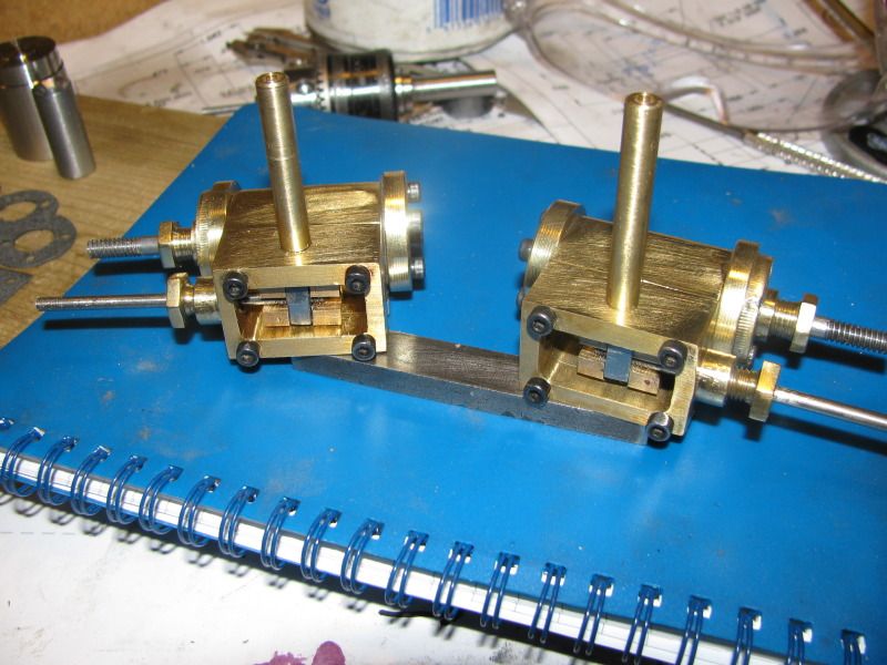
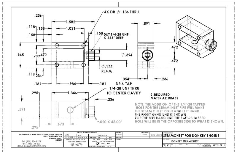
Tomorrow I have to work at one of my "real" jobs (The kind I get paid for). When I do get back to this engine to disassemble it and put in the gaskets, I will put the holes in the steamchests for the incoming steam.---and as someone was concerned about, this will make the cylinders right and left hand assemblies. I could keep both steam chests the same by having the steam enter at the end opposite the control rod, but I think I want to have it enter from the top, same as in the very first video in this thread.--I want to keep my plumbing the same. The walls on the steamchests are thick enough to drill and tap for my fittings that I will be using.
 
Brian Rupnow said:
SNIP>>>> (Resting on a much used and abused 1/4" parallel). <<< SNIP

Brian - That must be a Swiss made parallel. I think I have seen some cheese that the same company made ;D

Your progress is incredible considering you also have a real job. I cannot work at half your speed and all I have is my shop..... And my spouse.... and my two kids.... and their spouses.... and my six grandkids...

Keep up the great work. This this will be chuffing away before we know it.

Harold
 
Harold---Thank you. All is not as it seems. I have 3 jobs right now. The spinforming job has been on hold all week waiting for weldments to come in from an outside shop. The job which I can't talk about because I signed a Non disclosure agreement is on hold because I have to get some very proprietary cutters made up at an outside company. The reverse engineering design on the curb machine is temporarily delayed because of customer cash flow issues. This of course means that even with 3 concurrent jobs on the go, I get days where all I have to do is play in my toy shop.----Brian
 
This is the one part of making model engines that never seems to get any easier.---Making gaskets!! I have made up a number of dedicated weapons to help me in this quest, but its still a pain in the butt. Yes, printing them off at 1:1 scale does help if you use a light colored gasket material that you're not afraid to put thru your printer, but its not THAT MUCH better than the old "Trace around with a pencil" trick. The difficulty lays more in cutting them out and not having them tear out at the very narrow margins between bolt holes, pressure gallerys, and outside (as in atmosphere). Oh, I get it done-----it just takes time. I have tried all of the different blends of gasket goo, but my engines are generally apart 5 or 6 times before they go together to stay, and that instant gasket stuff doesn't like that too much, and its very difficult to keep the damn stuff out of places that you don't want it. The gasket material I use is about .025" thick, and is very forgiving if you have to disassemble something a few times to tweak it.
GASKETS002.jpg
 
A big thank you goes out to the gentleman from Indiana who sent me the brake details. I could have sussed something out on my own, but seeing how others approached the task makes it a lot easier for me.-----Brian
 
Brian,

I would suggest you try some PTFE sheet for your gaskets.

Since using it (for a few years now), I have never had a gasket break, like paper does after many assembles and disassembles, and also I have never had it leak, absolutely wonderful stuff.

http://madmodder.net/index.php?topic=1054.msg8338#msg8338

But do make sure that you buy the virgin sheet, without any etching on the surface.


John


Brian
Glad to hear you got the brake details. sometimes all it takes is a glimpse of the way the other guy did it to have it all come clear. I am working on brake drums at present and then will be winch drums to mount them on.
steve
 
Brian,

Not trying to teach you to suck eggs, but you will have fewer gasket Oops if you punch out the holes before you cut the shape.
Like most things this was another I learned the hard way.

Hope it helps

Best Regards
Bob
 
Got home tonight from one of my "real" jobs, and decided that I simply HAD TO come up with some steam inlet pipes to try these cylinders out!!! I looked at using 3/16" diameter brass tubing, but was kind of underwhelmed by how it looked. I modelled them and tried them on in the model, and somehow they just looked too small in diameter. I have a bunch of 1/2" brass hex rod that a good friend gave me, so I turned some of it to 1/4" diameter and drilled it out to 1/8" i.d.. I threaded one end to 1/4"-28 and then mounted the cylinders to a dummy baseplate and drilled and tapped the steamchests while everything was assembled (of course I had removed the valve slider and rod). I did this to ensure that the steam inlet tubes were absolutely verical. I didn't want them to "lean" in any direction when assembled to the final baseplate. Tomorrow I will install all the gaskets and see if it flies.
STEAMINLETPIPES001.jpg
 
Brian if you are going to be plumbing this one up with the cast fittings you could end up with a very chunky looking plumbing system using 1/4" od pipework, if you look at the pictures at the start of this thread the pipework would proportion down to something much smaller.

You should still be able to get 1/8" bore using 3/16 pipe and a finer 40tpi thread which would suit the exhaust side of things and come down to 5/32 with 3/32 bore for the delivery side of things maybe even 1/8" pipe.

Just out of interest Model Engineers handbook says a 5/32" OD pipe will supply enough steam for a 1" bore x 2" stroke cylinder so no risk of restricting the flow.

J
 
Agreed - in copper 1/8" for the steam and 3/16" exhaust is more than adequate for the 3/4" bore engines. Perhaps 1/4 copper for the exhaust for a bit more 'vacuum'
 
This morning I have GREAT NEWS for all who are watching this thread. The port modifications that i made worked good, and both cylinders respond excellently to the action of the valve. Now I am free to go ahead and build the rest of the engine, without having to worry about putting a lot of work into a project and then having it fail because the new port design wouldn't let the engines run.---Brian
 
Looking great Brian... I think we will have a runner!!!

Harold
 
Now that I have convinced myself that the changes I made to the cylinder porting does indeed work, I can now go ahead and post those drawings which were affected by my changes.
DONKEYCYLINDER.jpg

SLIDEVALVEFORDONKEYENGINE.jpg

DONKEYSTEAMCHEST.jpg

DONKEYSLIDEVALVENUT.jpg
 
Brian

Have you worked out the throw of the cam for the slide valve. ???

Just ran you're figures through the vormula I use and I'm strugling to get the same answer as you, or see how the valve would work.

I take it you're trying to use standard imperial cutters of 1/8" and 3/16" I think these are a little big for that steam chest

Better to use 3/32" and 1/8" cutters which is closer to the 2 and 3mm cutters used on the popcorn

With these cutters your .282 will be .234 on the valve vace

And for the slide valve.657 will be .623 and .345 will be .375

Hope this helps

Stew
 
The large size Benson that I have just got running uses 1/8" & 3/16" ports at the same spacing as your 0.282".

But the cavity under the puck is 0.423" long, total length of puck 0.75" and the eccentric throw 0.117" and it runs fine on 10psi and thats a much bigger piston & stroke.
 
Well there!!! Thats enough machine shop magic for me today. Tomorrow I will carve out the sides of the crosshead guide tubes for that "Oh so cool" look. Now---Concerning the ports.---I wanted this cylinder to be buildable without having to buy metric endmills. I have accomplished that. Does it work?---Well, it certainly works in the video. Is the throw on my cam going to be sufficient unto the task?---Well, I think so, but no, I'm not 100% sure, untill I've seen it run on its own. Did I apply a lot of scientific principles when designing this change?---No, not really. I seen what Stu had done, and it worked succesfully. I seen what a couple of other folks had done, and theirs worked succesfully. I made some block diagrams and seen what ports were covered and uncovered at different times in the cycle. I used some of Stu Harts math. I crossed my fingers and buried a black cat in my backyard at midnight. If the worst thing that happens is that I have to make a second cam because the first one I designed doesn't work (Which I doubt will happen), it won't be the end of the world. I'm not exactly certain what type of mania made me make the center port longer than the ones on each side, but i think it was the old "adjustable centerline" that got me. I would probably look at that a little more closely the next time. Hey, I'm happy!!! it works.
CROSSHEADGUIDES002.jpg
 
Back
Top