Brian's Donkey Engine

Home Model Engine Machinist Forum

Help Support Home Model Engine Machinist Forum:

This site may earn a commission from merchant affiliate links, including eBay, Amazon, and others.
Its not that big a deal to put a core in something like that.
They should core those things.
 
Pat the likelyhood of a 7/32" dia core failing or shifting are quite high, trying to pour an item with a wall thinkness of approx 1/32" and getting the whole mould full is also not easy as the metal will cool very quickly and then there is also the added cost of making and placing the core.

Another thing to remember is that Brian is using the relatively large 1/4" fittings don't fancy trying to core a tree of parts when the core is not much more than 1/16" which it would need to be on the fittings for 1/8" pipe.

Talking to people having things cast recently or pattern making and the general comments comming out of the foundrys are that if its under 1" dia core then it not really worth bothering unless its something particular like a steam passage. The cost of the extra metal used will outway the cost of teh core and the risk of problems.

J
 
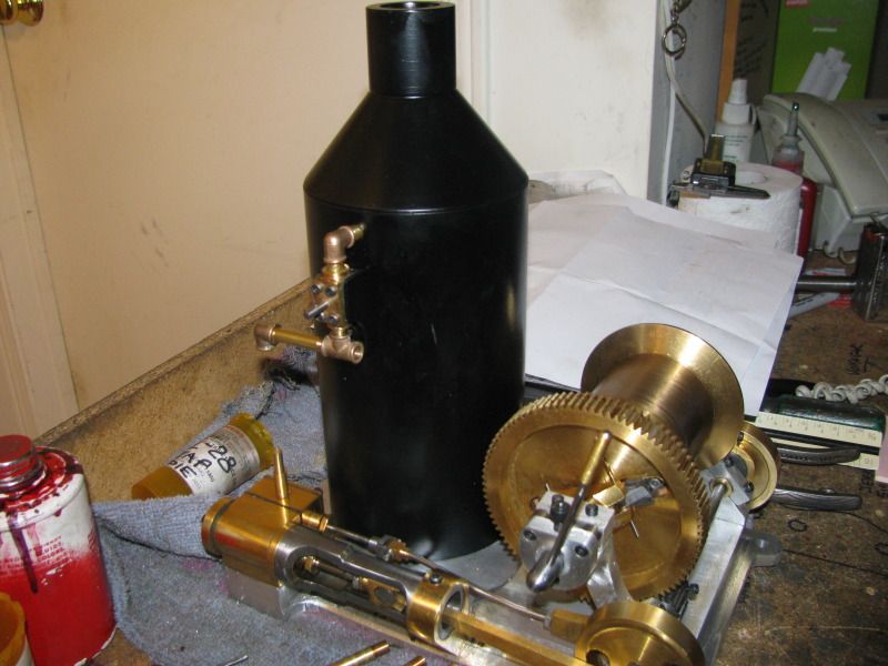
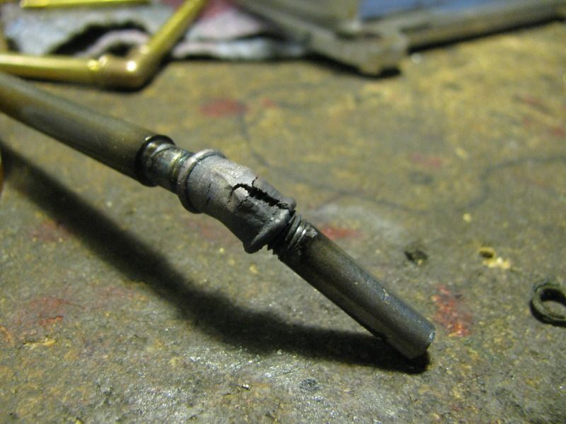
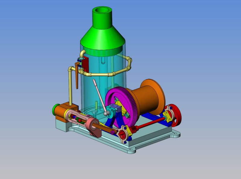
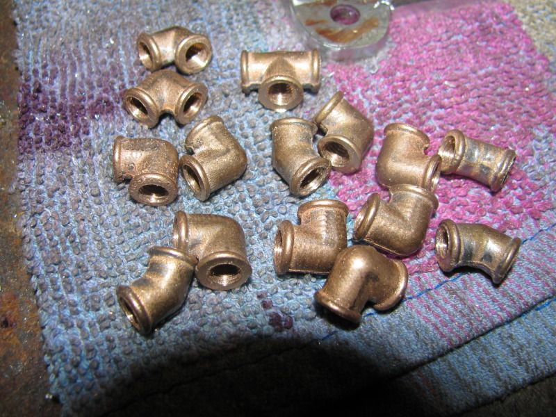
I'm back to playing with my Donkey. Last week when I had to disassemble everything to install the pinion on the looooonnng crankshaft, I just couldn't get all the binds out of the system to let it run correctly when I reassembled it, and when I did get them out enough for the engines to run, the damned things ran backwards. Of course, I was fiddling with the clutch, trying to get it to work correctly, and things just weren't working out. A few days break was needed. Today i snuck up on things by machining and tapping all the pipe elbows first. Then I retimed things and got both engines turning the correct direction. It still has some serious binds in it, but I find that if I loosen all the fasteners off untill the engine runs freely, let it run for half an hour, then tighten everything a bit, then let it run some more, I can tell when the engines start to rev faster it is time to tighten the fasteners another 1/2 a turn. This of course slows the engine down again untill it wears the tight spot in, then it speeds up again. Eventually, with enough repititions, all the tight spots should be gone and the engine should run much slower and smoother.
 
This is the clutch video I was trying to make last week when I got so disgusted and had to quit for a while. The engines are running much smoother now, (Turning the right direction) and the clutch is working pretty well as its supposed to. I have found one "caveat" that I may do something about, or I may not. I chose to make my winch drum 2.3" diameter, just because to me that looked to be about the right size to fit the scale of the whole project. The caveat though, is that with a larger diameter drum, the radius arm from the center of the winch drum to the center of the cable is longer, requiring more power from the engine to turn the winch, thus requiring that the engine run at a faster RPM than I really like. It "looks" right, but it would probably have been better if I had went with a 1.25" diameter winch drum. The part being lifted would raise more slowly, and the engine wouldn't have to work so hard. Of course, the question is, do I really care? I will probably fill the drum with one layer of cable for "looks" and the clutch may never be used again. This is a model engine, not a working engine, and unless I rent it out to the local elves or field mice, the clutch operation doesn't mean all that much.
 
Brian this comes back down to throttle control. If you up the psi on your compressor you will get more power but as you say the engine runs faster. Now leave the compressor at those higher settings but fit that control valve and you will be able to regulate the speed by controlling the volume of air but still have power and the rpm you want.

J
 
Brian

Looks like the clutch is working nicely. I agree that a smaller diameter drum would have given you a little more power and control but it will improve as the engine wears in and settles down. As Jason says, control valve at the engine would make a world of difference.

Jerry
 
Looking and running good Brian. There is definitely a method to your madness.
Just tell the garden gnomes that if they don't like it they can go back to using snails and a block & tackle.
Alan
 
I guess the time has come to mount my "steam" control valve and figure out my "steam" lines.
FULLASSEMBLYDONKEYWITHSTEAMPIPES.jpg
 
Nice running engine, Brian. The clutch and winch do work well.

Chuck
 
Thanks Chuck!!! I had posted this bracket once before today, but then it immediately underwent such major changes that I just deleted it untill I had it redesigned.---Brian
CONTROLVALVEBRACKET.jpg
 
Brian are you going to run the exhaust pipes back upto the cowel like the original? if so it may get a bit messy around the top of the boiler. I would be inclinded to bring the feed down the back of the engine and then tee off to each cylinder with a linkage to take the valve control to where the operator would be.

J
 
There! That takes care of my control valve bracket. Now I can mount it as per the solid model. Jason---There are no exhaust pipes per se'---Just steam escape vents on the underside of the cylinders.
BRACKETFORCONTROLVALVE002.jpg
 
I'm getting out of sequence here, but by adding one more counterbore to the elbow drilling jig I built the other day, it worked perfectly well to machine, drill, and tap the 1/4" pipe Tee.
pipeteeinjig002.jpg
 
Damn, Sam---Thats a lot of drilling and tapping and thread chasing!!! I didn't need all of those 90 degree elbows, but I had a jig and I was on a roll. The 45's were harder as i had to open the jig and turn the part end for end to machine/drill/ and tap both ends.
manyelbows-2001.jpg
 
Those fittings look great. I dislike tapping myself. And stop calling me Sam.
 
They look great, Brian! Of course, you are going to file off all the flashing then polish them up to a high luster, right! ;)

Chuck
 
Here we have a tale of bad luck, over confidence, or just plain old "dumb-assedness". First the good news----The boiler is painted with "Chassis Black" by VHT paints, which gives pretty well exactly the color and "hue" that I wanted. Not glaringly glossy, and yet not "flat black" either. The far side of the base is drilled and tapped for an air hose fitting in a very inconspicuous spot, and the air passage surfaces inside the boiler, where it connects via a flexible line to the "steam pipe" which exits thru the side of the stack and into my home made control valve. That part went very well. It was only while assembling all the piping to the cylinders that I discovered a mistake (can't call it anything else) that I had made. However I managed to do it, the cast 45 degree elbows are tapped in such a manner that they have a contained angle of 130 degrees, instead of the 135 degrees that they should have. This means that there is no way that I can assemble the piping as I had planned, as per the 3D model. I tried to heat one of the fittings, and "persuade" it to bend another 5 degrees, but the picture shows the result I had doing that. SO----I'm down four 45 x 1/4" cast elbows, and the minimum order from PM Research is $25. I toyed with the idea of machining 4 elbows from barstock, but I could never match the nicely cast 90 degree elbows that are okay. I'm kind of stuck for now, but I'll figure something out!!!----Brian
badelbows001.jpg

realbadelbow004.jpg
 
OUCH! Not good! You might have better luck bending the sections of pipe between the elbows.
 
Brian,
You are methodical and meticulous with all that you do. From your career as a designer, hot rod building, to hobby machining. I would be very surprised to find you are at fault here. I went back and had a second look at your fitting. Besides 1 or 2 being a tad off center they look great. There must be some unforeseen circumstance. Either the castings are not truly at 45 degrees or they cocked a bit in your jig.

Now for the fix.
Place the fitting back in the jig. Now that you know the amount of error you can shim the jig in the mill vice to what would essentially be "correct". Chuck your tap and chase the threads at the corrected angle. Yes, the threads will now be sloppy. Do your trial assembly to get all your plumbing the way you envision it to be. Then upon final assembly apply something like epoxy to the sloppy threads to create the seal.
No shame in it. I've used epoxy on pipe threads on all my compressor installations and they never leak down.
Alan
 
As its only on air you may get away with tightening up your die and cutting the pipe thread deeper which will give enough wobble to get the angle right, assemble with JB Weld or epoxy and it should be OK.

Was the jig machined wrong if they are all the same error??

You will likely also have to turn up some nutted unions as you won,t be able to screw the last fitting/pipe into place, it also makes disassembly easier, some thing like these

J
 

Latest posts

Back
Top