Boll Aero - my first engine build

Home Model Engine Machinist Forum

Help Support Home Model Engine Machinist Forum:

This site may earn a commission from merchant affiliate links, including eBay, Amazon, and others.
Great thread!
I enjoy reading and looking at each of your finished parts. This helps me make the same using completely different tools. Works out nice because your about 6 parts ahead of me. Currently working on compression screw and next is spray bar and thimble parts. Also had to go back and add the counter sinks on back plate. Somehow I missed those when drawing model and adding those complicated the part considerably doing it with my tools. Didn't even notice until I was looking at your nice screws in place :) oops! 3 steps back!
Anyway looking forward to your next update.
 
Hi Lane,

Thanks for your post! I was feeling reasonably good about my progress and then I saw the pic of those three beautiful engines in your latest post and I got completely demoralised! ;)

The speed and repeatability of CNC is definitely impressive. I love the work you are doing and the way you are tweaking the design to make it your own.

Cheers,
James
 
I've made a bit of progress in the last week or so. The crankshaft is close to finished. The 1045 steel I am using is a pig to turn. The drive belts on my lathe are knackered and the steel is so tough that if I took more than about a 10 thou cut the belt would slip and the spindle would just stop. My replacement belts have arrived so once this engine is finished I'll disassemble the lathe headstock and replace them.

Originally I said I was going to make the crankshaft as a single piece instead of the three separate pieces specified in the plans. Unfortunately I didn't think through the machining sequence properly, and so I've ended up having to use a separate crank pin after all, although I haven't drilled the hole for this yet.

2016-01-15%2016.37.34.jpg


2016-01-16%2017.12.37_1.jpg


2016-01-17%2018.33.25.jpg


2016-01-21%2022.09.10.jpg


2016-01-21%2022.45.59.jpg


At this stage I couldn't help myself and had to test fit it together to see what the engine would look like with a crankshaft installed.

2016-01-21%2022.47.39-1.jpg


Next part to make was the collet for the prop driver. This was a pretty simple turning job out of brass. I added a small lip on the backend to assist with removal if it becomes difficult to get off the crankshaft later.

2016-01-24%2010.18.26.jpg


With the collet made and without changing the topslide angle from the 10 degrees used to turn the taper on the collet I started work on the prop driver. I've turned up the body of the part. I now just need to turn the internal taper, part it off and add the knurl on the front face.

2016-01-24%2010.37.29.jpg


Hopefully I'll be able to finish these parts off this weekend and make a start on the con rod.

Only a few parts remaining now but obviously I still have to tackle the the most difficult part being the piston (in terms of tolerence of fit at least).

Cheers,
James
 
Hi Lane,

Thanks for your post! I was feeling reasonably good about my progress and then I saw the pic of those three beautiful engines in your latest post and I got completely demoralised! ;)

The speed and repeatability of CNC is definitely impressive. I love the work you are doing and the way you are tweaking the design to make it your own.

Cheers,
James

Thanks for kind words on my work. Im a better photo guy then machinist :)

Cnc tools have some very cool benefits and some very big drawbacks.
Not much room for errors in process, setup and tools. Only e-stop and by then tools and parts are destroyed. Time it takes to go from design to a part can vary from an hour to couple days. Much like you noted on the spray bar fab were valid and I spent days working out feeds - speeds- tool paths and model designs to make just 1 part with a 3-4 failures.
Then comes the cool benefit of repeat your successful setup / process and make a pile of good ones. Kind of the reason for making a couple complete assemblies. After all that effort why not make another in 1/10 the time.

I can safely say I have learned more in the last month building an engine or any design by someone else for that matter then in the previous year doing my own projects. It was easy for me to get in a rut of making my stuff with setups that are proven and not learn or challenge my skills and tools.
Also looking at threads like this to inspire me to take on the challenge.

You mentioned demoralized :) "don't be" I want to inspire like you and others have done. I have no doubt this project is going to test my metal! Might need to work out a trade with you :) or other builder on some parts best made on a lathe. I don't know if I can make useful or functional crankshaft / piston / cylinder. Thinking this might be only way to get one running .
Anyway great thread and always enjoy the updates and pictures.
Lane
 
After drilling a 0.250" hole through the prop driver to I needed to cut the internal taper to mate to the brass collet I had previously made. The issue was that the 0.250" hole was going to be way too small for any of the boring bars I have, so I was pondering how best to grind a small boring tool from a piece of HSS. Digging through my odds and sods of HSS tool steel I came across a small hand ground boring tool I didn't even realise I had. It was in amongst the dozens of odd custom ground tools that came with the lathe when I purchased it.

2016-01-30%2014.29.14.jpg


This worked perfectly and I was able to easily cut the internal taper to mate to the collet. The next challenge was that the plans called for the face of the prop driver to be knurled with a straight knurl. I only have one knurling tool with fixed wheels to cut a diamond knurl. With no other option, I mounted the knurling tool face on to the workpiece and plunged it into the part. The result actually turned our really well and looks just like the prop drivers I have on a couple of vintage diesels I have from years past.

2016-01-30%2015.18.50.jpg


2016-01-30%2015.19.12.jpg


2016-01-30%2015.19.59.jpg


2016-01-30%2015.20.33.jpg


2016-01-30%2015.22.43.jpg


The next part I decided to tackle was the con rod. I had some 0.240" thick alloy plate which I needed to reduce to 0.160". With no mill I need to do any milling operations in the lathe, so I cut a section, mounted it in a vice attached the vertical slide and milled it to thickness.

With that done I cut a blank 0.340" wide, and mounted it in the four jaw chuck. I centre drilled the end and using a live centre in the tail stock for support, started turning the shaft.

2016-01-31%2014.52.33.jpg


2016-01-31%2015.17.55.jpg


2016-01-31%2015.32.40.jpg


2016-01-31%2016.39.40.jpg


That's where I ran out of time last weekend. I'm off out to the workshop now to see if I can make some more progress on the con rod.

Cheers,
James
 
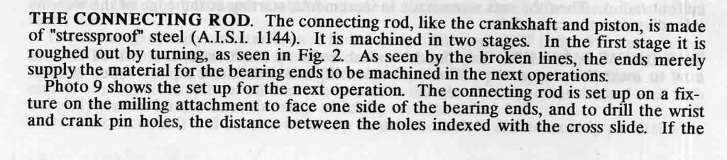
Wow - it's been a while since I've had time to update this thread. Lot's of family commitments have meant I've not had much time in the workshop over the last few weeks. I have had a couple of failed attempts at producing the conrod though...

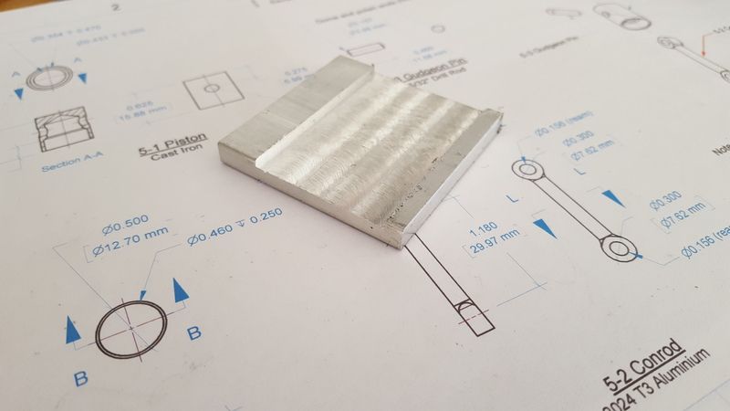
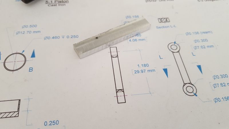
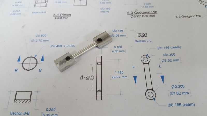
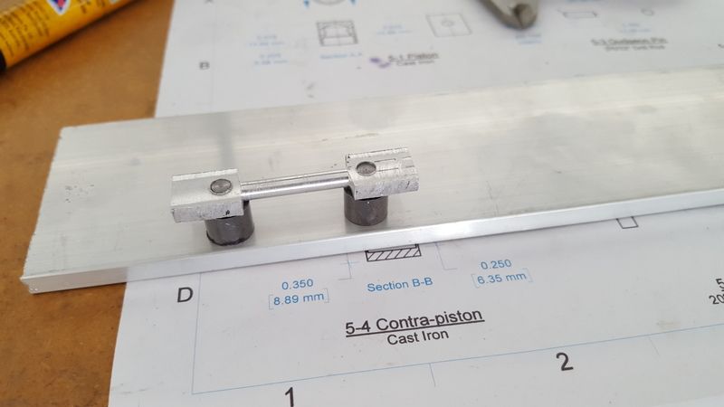
My first approach which I had started on in the previous post was to turn a section of flat aluminium and then mill the radius' on either end. At first this looked like it was going to work out reasonably well. I had turned the centre of the rod and drilled and reamed the pin holes and was reasonably happy with the result.

c1e1cac1-6d2c-49d2-b4a3-e96a23d85ffe.jpg


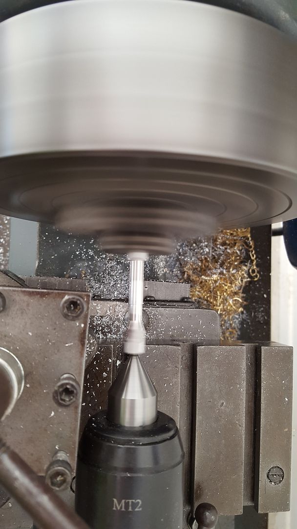
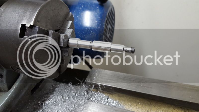
I had then planned to emulate an approach I'd seen on another website where a clever chap had built a modified version of the Boll Aero which he has called the 
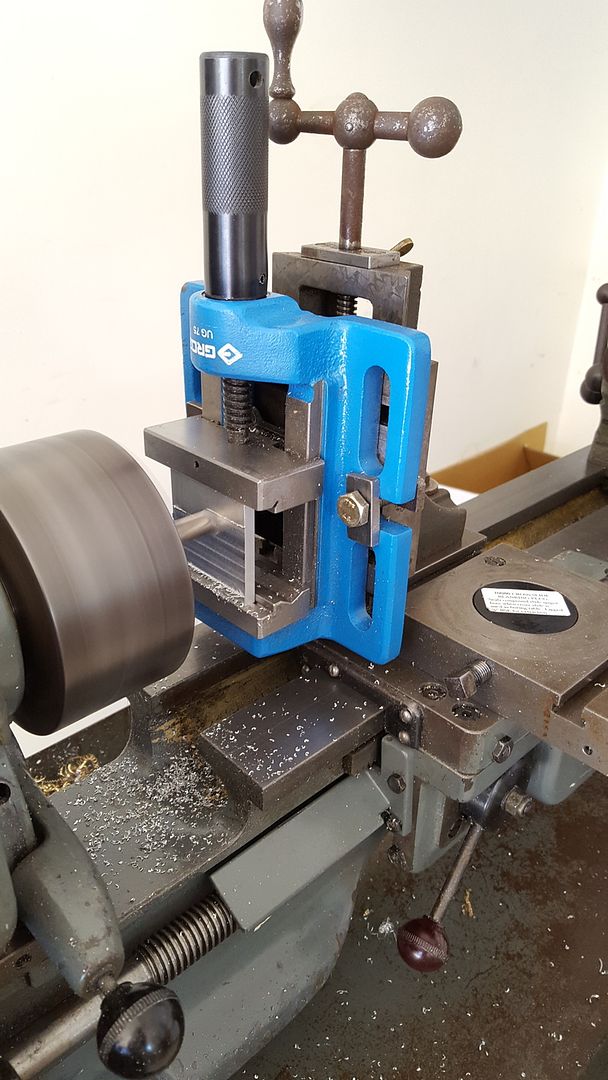
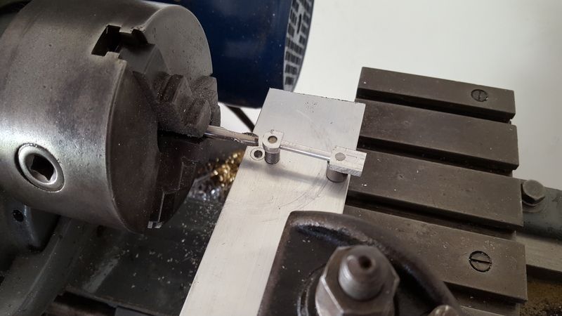
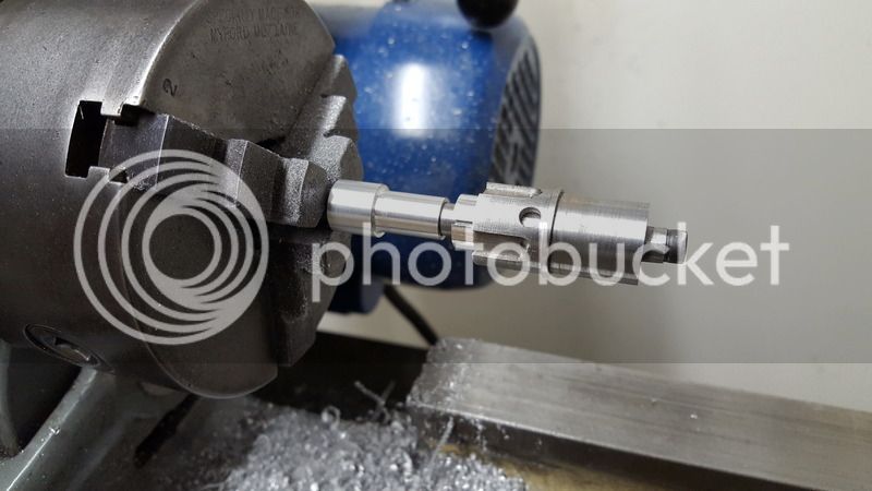
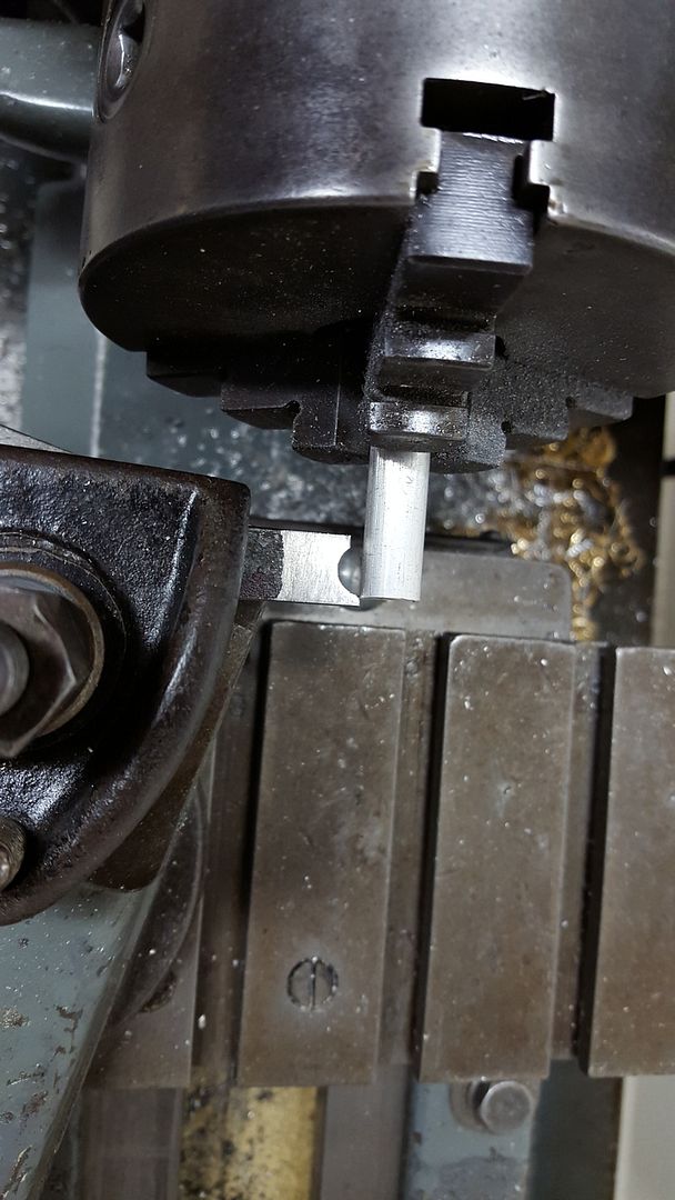
Nelson 2cc. At the bottom of that page is a picture what I thought was a rather clever approach to turning the conrod. The next sequence of photos show my attempt to replicate that approach.

2016-02-28%2011.15.09.jpg


2016-02-28%2011.23.44.jpg


2016-02-28%2012.26.03.jpg


2016-02-28%2012.26.41.jpg


2016-02-28%2012.26.55.jpg


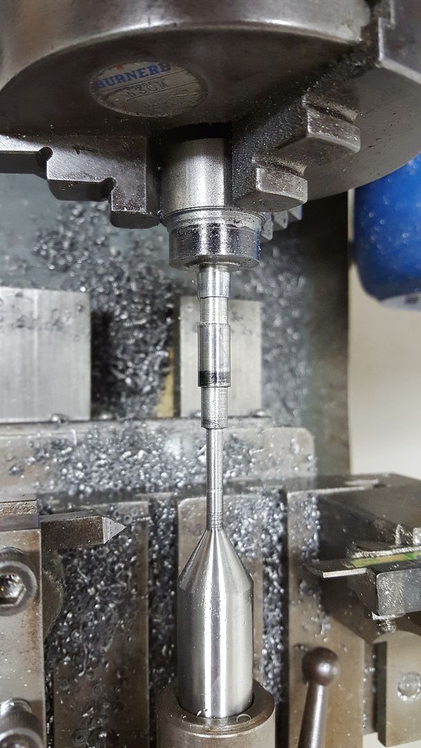
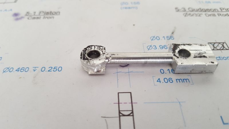
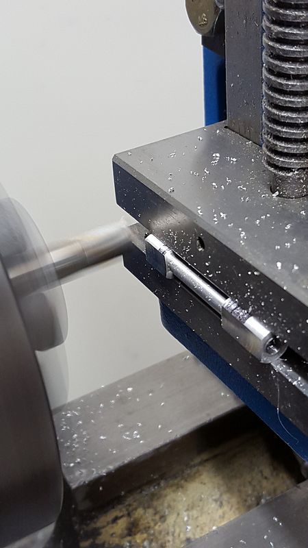
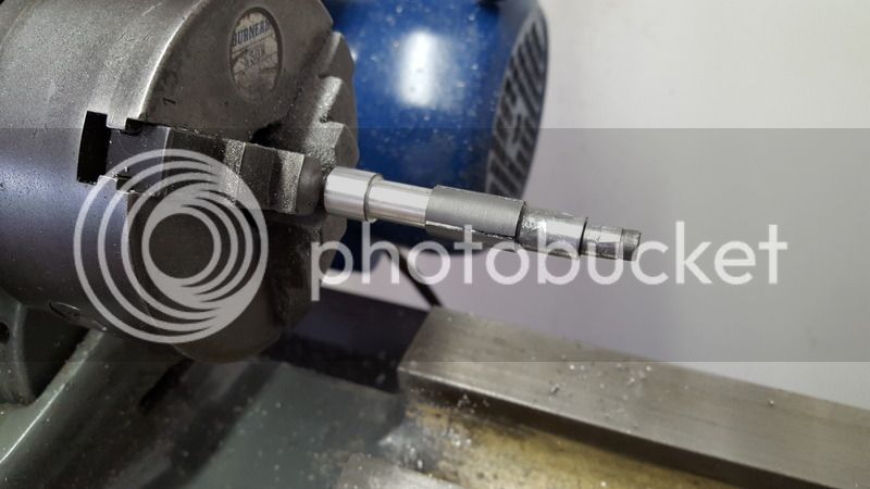
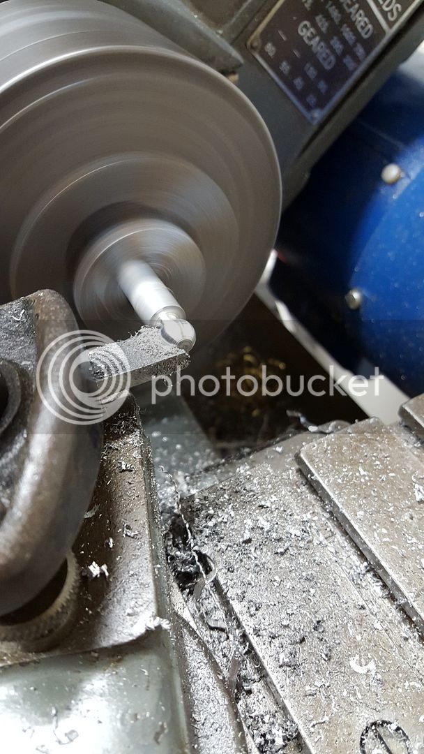
As the last couple of photos show, my result was less than ideal. My setup clearly had way to much flex and play in it and the conrod bounced about during milling. It felt a bit dodgy, and eventually the mill bit and twisted the conrod and gouged the shaft.

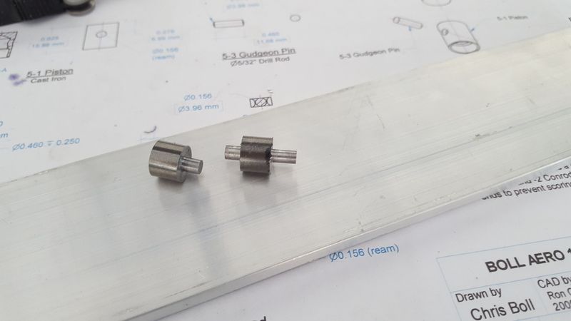
I wasn't feeling to optimistic about this approach so decided to try an new tactic. I had seen an alternative way of making conrods as described by Ramon Wilson in his 5cc Super Tigre build.

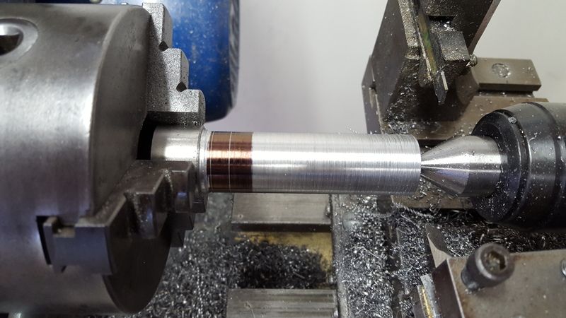
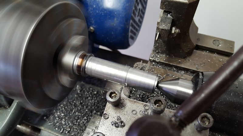
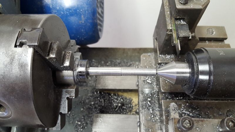
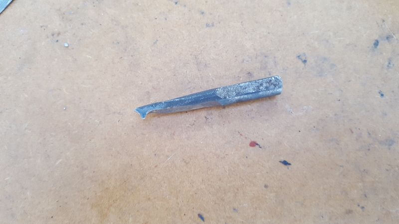
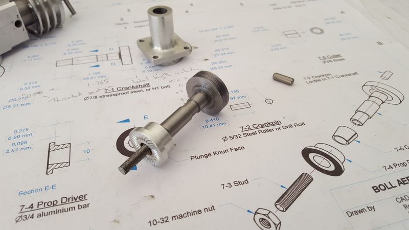
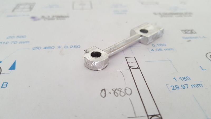
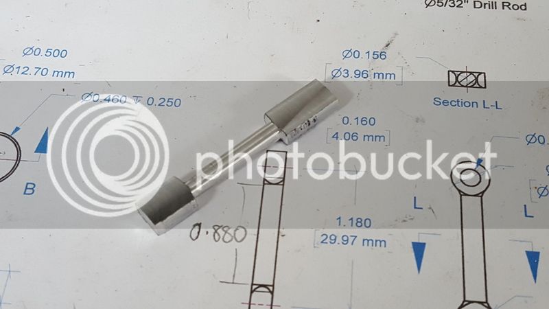
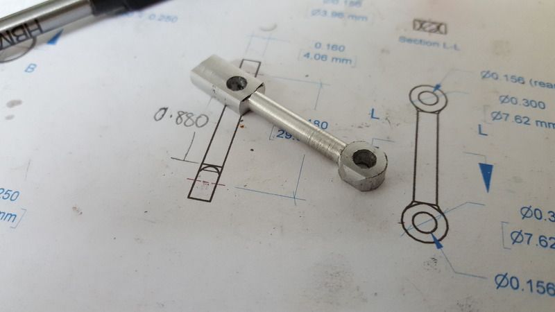
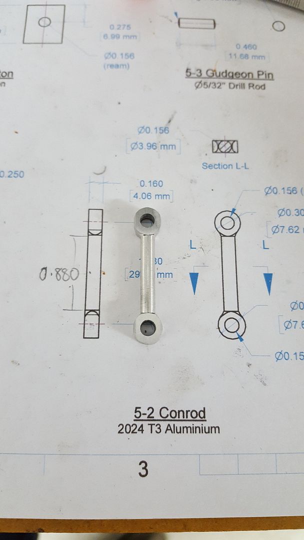
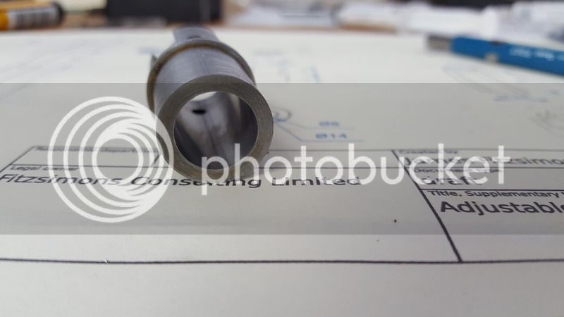
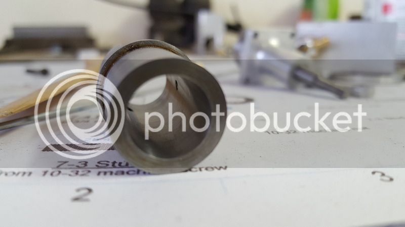
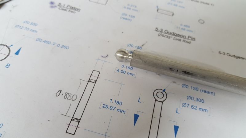
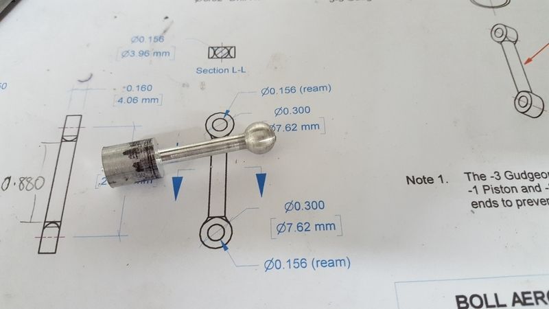
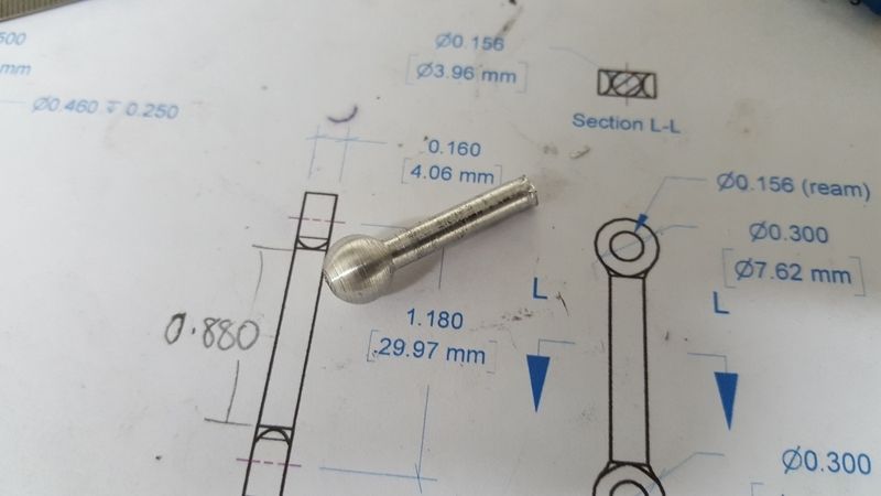
This time I started with a length of aluminium bar and used a radius tool I had made from some scrap flat steel I had to hand. The radius tool turned a reasonably decent looking ball. I then turned the shaft and parted the work piece off with enough material left to turn the ball at the other end. Next I drilled a hole through the centre of another short piece of alloy rod the same diameter as the conrod shaft. I sawed the alloy rod with the hole length wise, then used this to clamp the shaft of the conrod and hold it in the 3 jaw so I could turn the ball at the remaining end. Unfortunately as the final picture shows stress of turning with the radius tool snapped the shaft of the conrod.

2016-02-29%2021.53.38.jpg


2016-02-29%2022.03.15.jpg


2016-02-29%2022.08.07.jpg


2016-02-292022.25.57.jpg


2016-02-292022.56.48.jpg


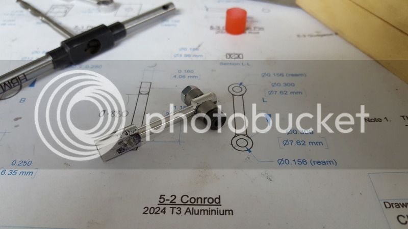
I feel like this approach has merit. There are a couple of things I plan to try next. I will turn the blank to close to finished diameter before any other operations. This will dramatically reduce the amount of material the radius tool needs too remove and therefore the amount of sideways stress placed on the conrod in the final operation. Secondly, I plan to rework the radius tool slightly to remove the width on each side of the radius. The profile is far to square on either side of the half circle. If these were sharper shapes, they would cut more easily and reduce the side loading on the work piece.

Unfortunately it's going to be a few more days before I can get the time to try all this, but having some time to think about it may unlock some more ideas.

I always expected the conrod, piston / contra piston and lapping to be the most difficult aspects of the engine.

Of course if I had a mill and a rotary table this would be so simple... but where's the fun in that ;)
 
Without a mill you do have some difficulties

Maybe an approach you might consider is to bore the big end and little ends to size in a piece of suitable diameter rod with some overhang each end, then machine the central part of the rod using the chuck one end and a live/dead centre the other end. Small cuts so as not to overload the weakened end where the hole is. Then use the dreaded hacksaw and linisher/grinder to get the rounded shape of the ends of the conrod. I am not too ashamed to say I have done this many times .... Ed
 
Roboguy -

The "MLA Diesel" uses a connecting rod that has some similarities with the one you are making. I built my "MLA Diesel" with the help of a milling machine and rotary table, but the instructions that came with the kit tell how to make everything on a lathe. I sent an email to Andy Lofquist, who designed the "MLA Diesel" and markets the kits, asking for permission to post his copyrighted text, drawings, and photo of his approach for making this part, for your possible benefit. He graciously agreed. I have no ties with Andy, but I feel it is appropriate to thank him for his assistance by posting his website of lathe accessories and Diesel kits here.
http://www.statecollegecentral.com/metallathe/
Text%201.jpg
[/URL]


I hope this gives you some more ideas on how to proceed.

Bob
 
The method Bob documents reads well. I did some snooping and youtube spat out [ame="https://www.youtube.com/watch?v=4kVnTZ3eaVw"]this approach[/ame]. While its done using a mill I would think it could be adapted to a lathe with vertical slide. This guy gets his fingers a bit close to "high speed spinning things" for my comfort levels. However I would think the use of needle-nose pliers or some other tool could be used to get fingers out of the way. Anyway it is another approach to consider.

Cheers,
James.
 
Thanks for all the replies guys. It certainly helps with the motivation to post if you know that someone out there is reading your rambles!

Who knew there were so many challenges and so many solutions for making what seems like a very simple part. Those replies have all taught me something more. I intend to have another crack at my last method although I will improve my radius tool as per my last post before trying. I also intend to try some slightly different alloy bar which I think will have a higher tensile strength and is probably better material for the conrod anyway.

I had always intended to mill the faces of the rod ends using exactly the approach illustrated at the end of Bob's post, so it's encouraging to see that I am following a tried and true approach there.

If my next attempt doesn't work out then I'll probably do as Ed suggested and fall back to a file to get the radius on the ends.

Will keep you posted!

Cheers,
James
 
Hi all, I haven't given up or fallen of the face of the earth. I've been super busy with work family etc and haven't had much time out in the workshop for the last couple of months. After about four failed attempts at making the con-rod I probably needed a wee break anyway to recharge my enthusiasm.

I decided to go low tech with my last attempt to make the con-rod and although the result is not perfect, I think it will be good enough for my needs for this engine.

I started out with some alloy rod which I turned down to 0.300". This was a mistake which you will see later, but hopefully won't effect the overall functionality of the finished part. I then turned the centre section of the rod to 0.156" for the correct length. Having something that now looked like an odd shaped bar bell I needed to mill flat both ends of part.

2016-05-22%2016.10.28-1.jpg


2016-05-22%2016.52.04.jpg


Next I drilled and reamed the gudgeon and crank pin holes at each end. With that done I was back to forming the dreaded radius on the ends. This time I turned up some 1215 steel filling buttons and sandwiched one end of the rod between them.

2016-06-12%2016.36.43.jpg


I then carefully filed the radius using the filling buttons as a guide.

2016-06-12%2016.59.09.jpg


2016-06-12%2021.07.21.jpg


Here you can see the results of my earlier mistake in turning the rod to 0.300" along the length at the start. Each side of the radius on both ends of the rod has a second radius along the same axis as the rod. I don't think this will be enough to materially affect the strength though, and as I've said before this engine isn't likely to see a whole lot of running so I'm going to forge ahead and hope this con-rod holds out.

So, almost there. Last major steps are to lap the cylinder, and turn the piston and contra-piston and lap those to the cylinder.

To that end the next thing I plan to make is a lap for the cylinder. I plan to replicate one like this.

DSCF0415.jpg


You can see more about how the lap works in the build thread here http://modelengineeringwebsite.com/Super_Tigre_6.html

Question - if my cylinder is 1.402" long, would I be correct in assuming my lap needs to be a little bit longer than that? I am guessing that using a shorter lap than the length of the cylinder would be a bad idea as it would be difficult to get a consistent finish along the whole length, or is this fine as long as you move the cylinder up and down the lap as you are lapping?

Cheers!
James
 
Over the last week I've managed to get a couple of nights out in the workshop to make the lap for lapping the cylinder. I decided to try my hand at drawing it up in CAD first. I've never really done any CAD before and so thought it about time I learn the basics. I used FreeCAD which seems a little rough round the edges but appears to be being actively developed. If anyone has any suggestions for good (preferably cheap or low cost) CAD packages please let me know.

I've learnt a bit with my lap design already. The thin end of the taper on the mandrel is just to narrow meaning I had to use a very very thin boring bar. I actually ended up making one from an old HSS drill bit as I didn't have anything suitable, but it simply had too much spring in it and it was very difficult to get the internal taper to match the taper on the mandrel.

Here's the lap components and then the assembled lap.

2016-06-23%2022.17.46.jpg


2016-06-23%2022.18.26.jpg


I then mounted the lap in the 3 jaw chuck and turned the lap to size. A final test fit with the cylinder has it pretty much bang on and ready to go.

2016-06-23%2022.34.01.jpg


2016-06-23%2022.34.43.jpg


Tomorrow I plan to try my hand at lapping!
 
Looks great. I remember seeing that lap design in the Super Tigre link. One thing maybe you can explain I never quite understood. The removable segment closer to the chuck [1] I assume is to allow the sleeve to extend over the lap length. But why does this [blue segment] have to be removable & bored to same mandrel taper? Couldn't you just turn that portion down from the same stock, reduce as necessary to accommodate bore ID & start the tapered portion from the end to suit the lap segment? Hopefully this question makes sense. Attaching sketch.

Also if its not too late, it would be interesting to measure your lap barrel before/after lapping to see what amount gets consumed during the operation.

2016-06-25_9-54-11.jpg
 
Question - if my cylinder is 1.402" long, would I be correct in assuming my lap needs to be a little bit longer than that? I am guessing that using a shorter lap than the length of the cylinder would be a bad idea as it would be difficult to get a consistent finish along the whole length, or is this fine as long as you move the cylinder up and down the lap as you are lapping?

Cheers!
James

Length of lapping tool for cylinder must be 3-4 times longer than length of cylinder to preventing "bell" formed cylinder.

Lets take a look at a typical lapping job - that of producing a fine finished bore and piston for an IC engine. In fact, piston and bore are both lapped in separate operations (NOT both together). All of these operations will be carried out in the lathe (and I need hardly mention the importance of keeping lapping compounds off the machine, particularly the chuck and slideways). For the bore an expanding lap is ideal, and this should be some 3-4 times the total length of the bore. The first grade of abrasive would be mixed with light machine oil (10W or lighter) and liberally coated on the inside of the workpiece. Similarly, the slurry would be added to the outside (and inside assuming it is of the ventilated type) of the lap. The lathe would be started at about 300rpm (for a nominal 1" bore) and the lap passed rapidly through the bore, keeping it moving back and forth without it coming out the bore. How to hold the lap? well, perhaps the best way is with a 'floating' tailstock holder, and failing this holding with the hand is a method as good as any. Be careful when holding the lap by hand as it's possible it may jam, hold it lightly and expect the unexpected. Remember also that unless the lap is maintained dead parallel with the bore (an almost impossible task) it will tend to bell-mouth the bore a little - hence the reason for making the work a little longer than finished size and trimming to length later. When the inside of the bore has achieved an all-over grey appearance, with the fine scratches appearing even and criss-crossing both ways, and with no evidence of any deeper scratches (as might be left by the reamer) it's time to move onto the next finer grade. The work will have to be removed from the chuck to clean it properly, and this should be done with clean paraffin oil followed by hot soapy water. The same procedure applies to the lap and all traces of the abrasive must be removed. The process continues until you reach the 'flour' grade of abrasive by which time the finish on the workpiece should be very fine indeed. A final polished finish, should this be deemed necessary, can be achieved using metal polish (diluted Autosol, or some liquid chrome cleaner). The lap should be a separate 'finishing' lap so there is no chance of contamination with the coarser grades of abrasive which might be embedded in the main lap. The piston is treated in a similar way except of course the lap is female. Work will continue with the coarse abrasive until (using the un-trimmed bore as a gauge) the piston will not *quite* enter the bore. At this stage finer grade abrasives are used and work continues until the piston will just enter the bore tightly. At this stage, it is usual to finish mating the two parts by using metal polish and briefly using the piston to lap the bore directly. Great care needs be taken but this method ensures that the fit is good for the entire length of the bore.

To check fit is correct: dry piston/cylinder --> piston goes tight into cylinder. Oiled piston/cylinder --> piston is loose in bottom of cylinder and tight in top of cylinder. Also cylinder is tapered to make good compression and easy to start engine. Parallel cylinder will loose compression very soon under working temperature. The tapered cylinder will expanding under working temperature to parallel cylinder without loose compression.
 
The removable segment closer to the chuck [1] I assume is to allow the sleeve to extend over the lap length. But why does this [blue segment] have to be removable & bored to same mandrel taper? Couldn't you just turn that portion down from the same stock, reduce as necessary to accommodate bore ID & start the tapered portion from the end to suit the lap segment? Hopefully this question makes sense. Attaching sketch.

Hi Petertha,

The removable section you have highlighted in blue is used to knock the lap sleeve back of the mandrel if you want to loosen the lap (or replace the sleeve). If you have over expanded the lap you can just back off the screw and loosen the chuck and tap the screw which will cause the sliding section to push the lap sleeve back down the mandrel taper. Apologies for the clumsy explanation, hopefully the attached plan will help clarify things

The mandrel isn't actually tapered all the way up, pretty much as far as your green dashed lines go, then it is parallel. The sliding section is just a loose fit over the parallel part of the mandrel.

Here is my plan - apologies for all the drawing rules I've broken - I'm just finding my way here!

lap.jpg


Also if its not too late, it would be interesting to measure your lap barrel before/after lapping to see what amount gets consumed during the operation.

I measured the lap sleeve, but of course as you expand the lap during lapping the sleeve gets bigger. I should have measured the inside of the cylinder bore but didn't think of that until after I'd done the lapping.
 
Length of lapping tool for cylinder must be 3-4 times longer than length of cylinder to preventing "bell" formed cylinder.

Hi Jens,

Thanks so much for your detailed reply! Unfortunately I'd already done the lapping by the time I saw this so I may have a bell in my cylinder. Oh well, it's all a learning experience so I'll see how this one goes and if it doesn't work out I can always make another one!

Cheers,
James
 
Well, my first attempt a lapping is done. I'm pretty sure this is a long way from perfect, but this whole engine is just a skills development / learning experience so if I can get it to start and the end that will be a win!

Lap after lapping
2016-06-26%2013.25.06.jpg


Inside of the cylinder bore now looks pretty good.
2016-06-26%2013.25.32.jpg


In this photo you can still see some very slight scratch marks. To be honest the photo looks worse than reality.
2016-06-26%2013.26.01.jpg


Next step will be turning up the piston and contra piston.
 
Hi Jens,

Thanks so much for your detailed reply! Unfortunately I'd already done the lapping by the time I saw this so I may have a bell in my cylinder. Oh well, it's all a learning experience so I'll see how this one goes and if it doesn't work out I can always make another one!

Cheers,
James

:)

No problem to relap with a longer lapping tool, it must be same resistand in all ways in whole length of cylinder under lapping. Never stay in same place under lapping, move in both ways while you are lapping the cylinder ---> you are creating cross hatching wall in cylinder. Wash and check, there is not tool marks and dull gray. Also it's very bad idea to lap the cylinder/piston to a mirror finish. Do it same with contrapiston but with tight fit into cylinder, still movable with compression screw/by pressure of compression.
 
  • Like
Reactions: gus

Latest posts

Back
Top