Boll Aero - my first engine build

Home Model Engine Machinist Forum

Help Support Home Model Engine Machinist Forum:

This site may earn a commission from merchant affiliate links, including eBay, Amazon, and others.

Roboguy

Well-Known Member
Joined
Aug 10, 2015
Messages
60
Reaction score
34
In my introductory post I said I would be starting my Boll Aero build shortly. Well it's taken me a week or so to get under-way, but I finally got started last night.

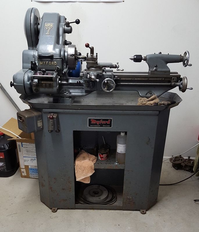
I have minimal equipment at this stage, and I chose the Boll Aero due to the low part count, and the fact that it can be built entirely with a lathe and a drilling machine. I have a Myford Super 7 lathe and a very budget drilling machine (lesson learned there!) and am slowly amassing the requisite hand tools, drills, taps, dies, reamers etc.

a6c5f195-bcfa-4c9a-9a86-28f466da94e2.jpg


I've spent quite a bit of time already thinking through the machining sequences and how I will hold work pieces. I've written up a series of steps for the first three parts I plan to machine. Those being the crank case, the backplate and the main bearing (nose piece).

One challenge I have been grappling with is how to accurately drill the holes in the three parts given I don't have a mill and my drilling machine is a bit rubbish. The plan I came up with was to make a drilling jig that I would use to position the holes in all three pieces so the line up correctly.

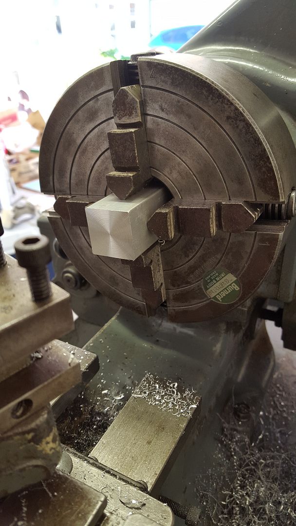
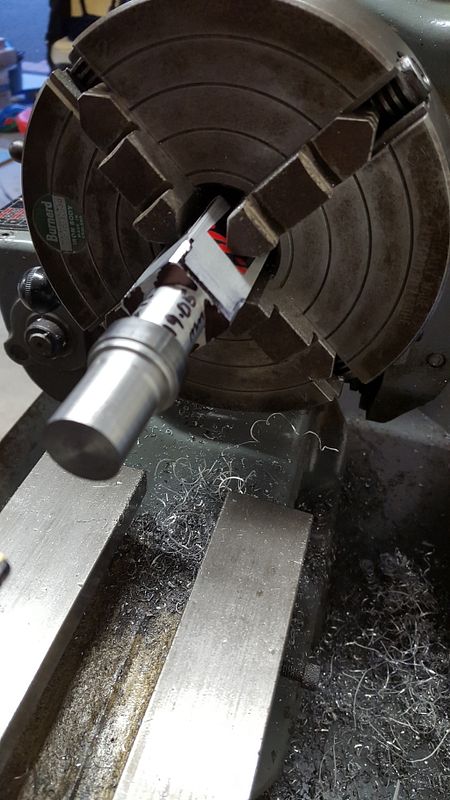
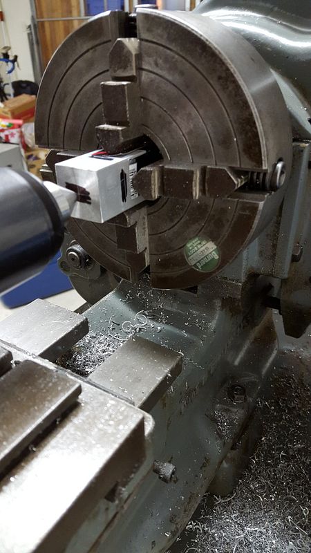
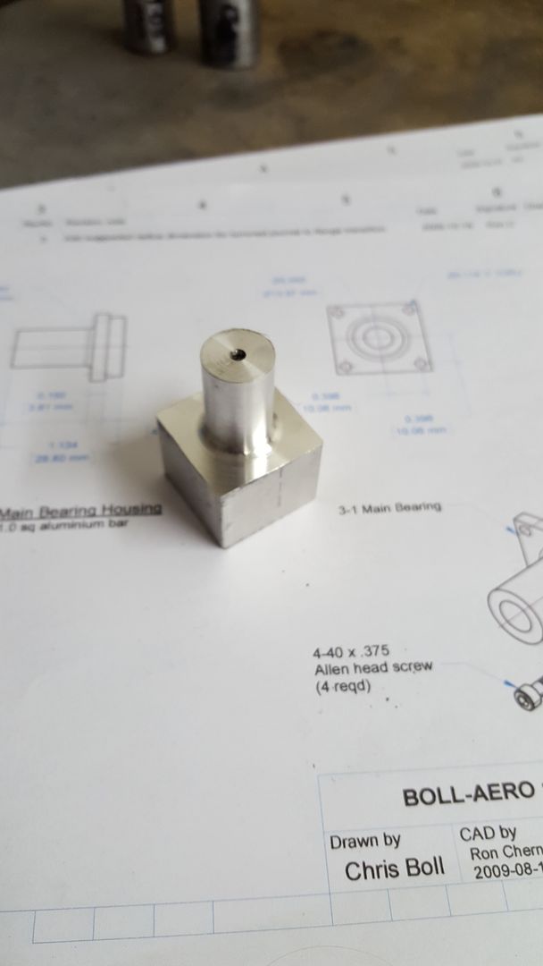
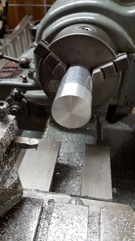
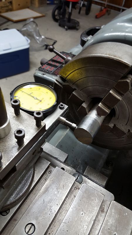
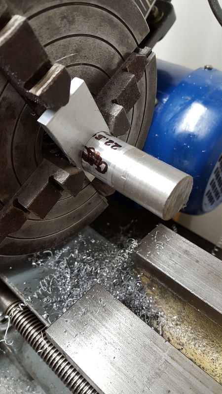
To that end I started with a hole guage for the main bore. This will be used to locate the jig over the crankcase for drilling. This was the first time I had ever used my four jaw chuck. I made the tool post mount for the dial indicator as I thought that would be useful when it comes to squaring up the crankcase and other parts soon.

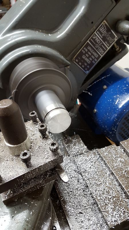
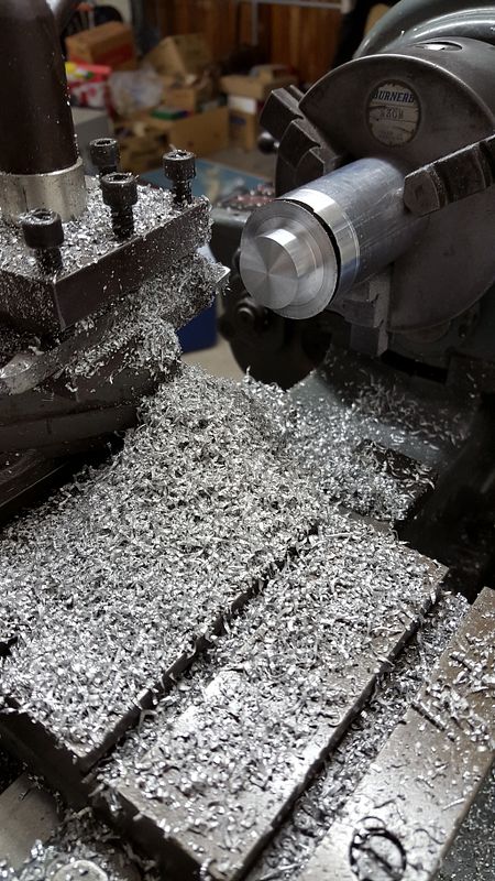
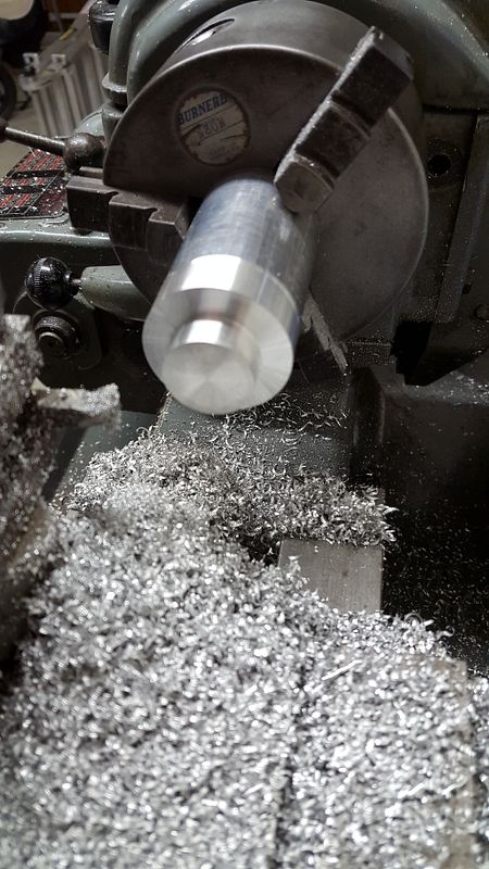
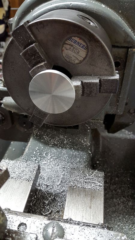
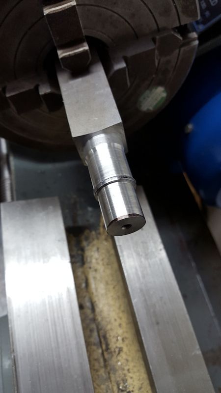
Turning up the hole gauge
2015-11-05%2020.38.30.jpg


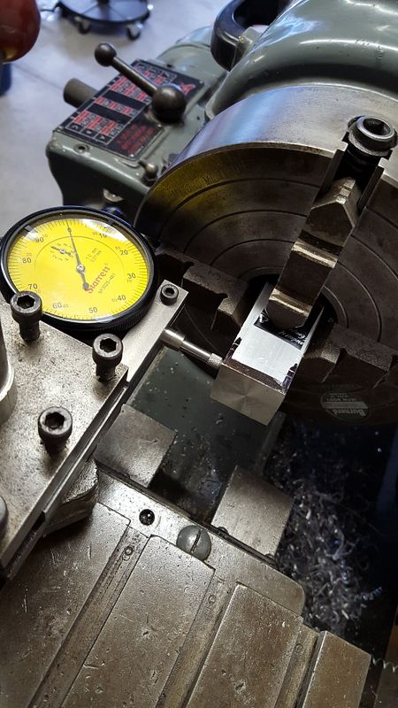
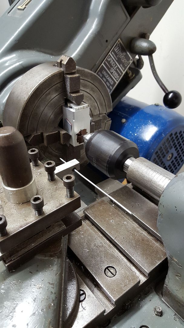
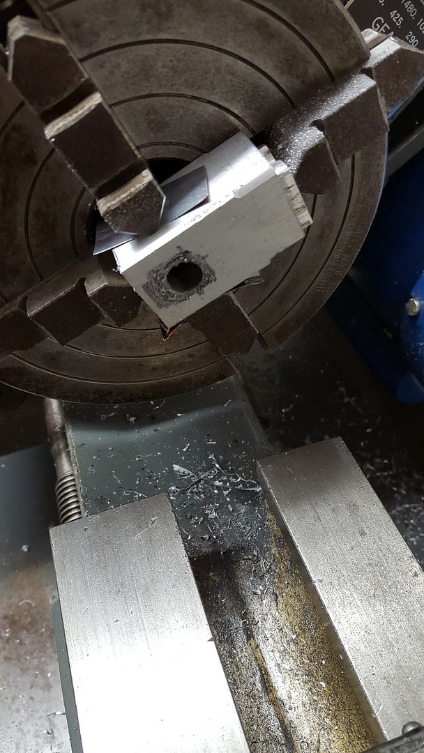
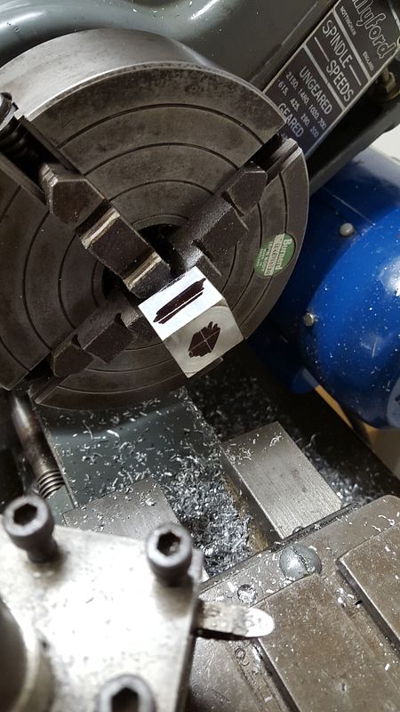
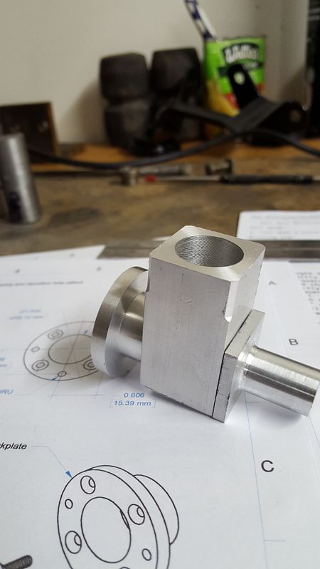
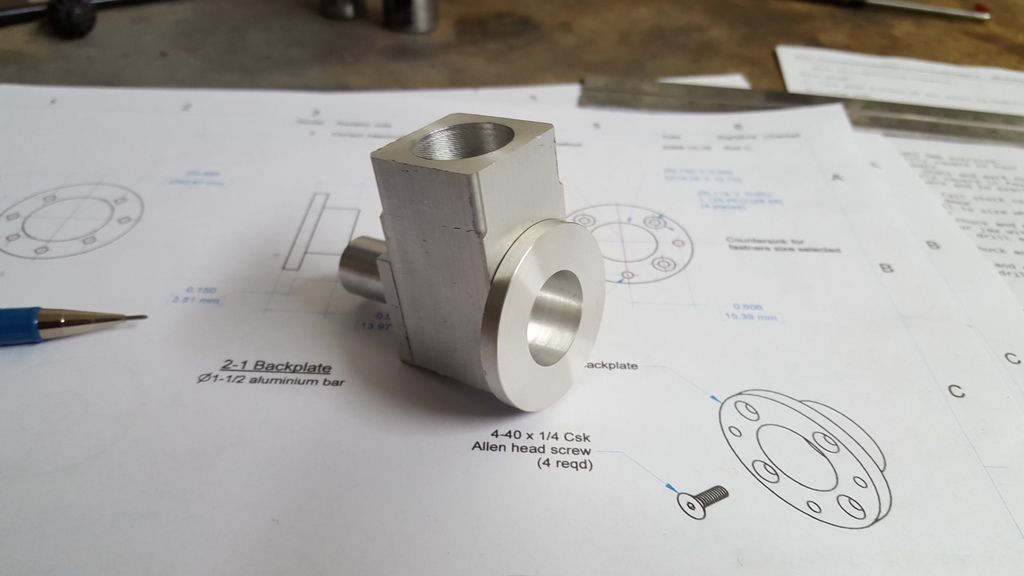
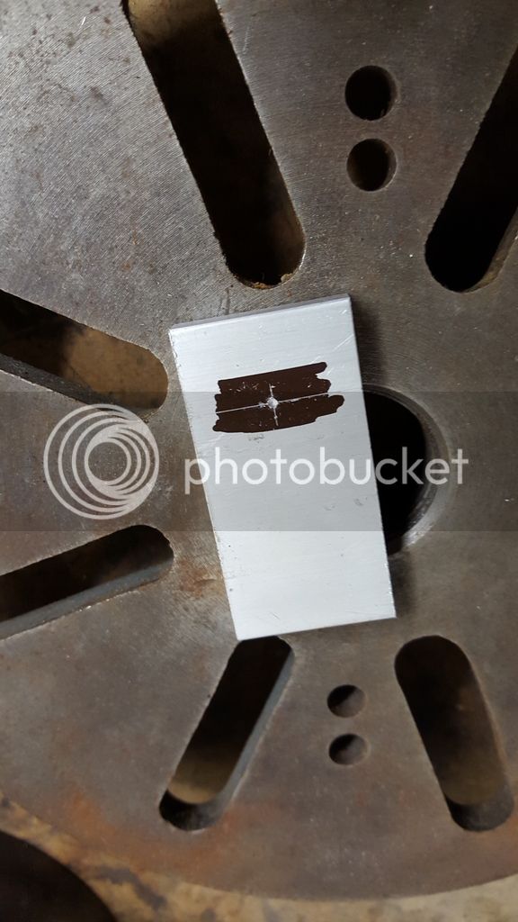
Marking out the drilling jig
2015-11-05%2021.42.10.jpg


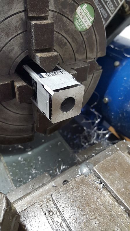
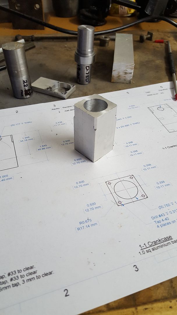
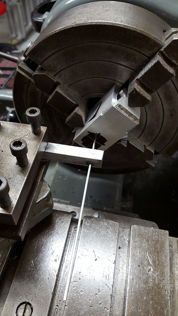
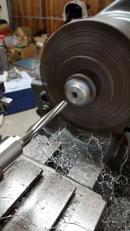
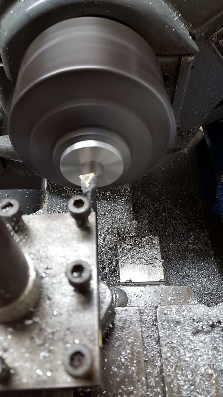
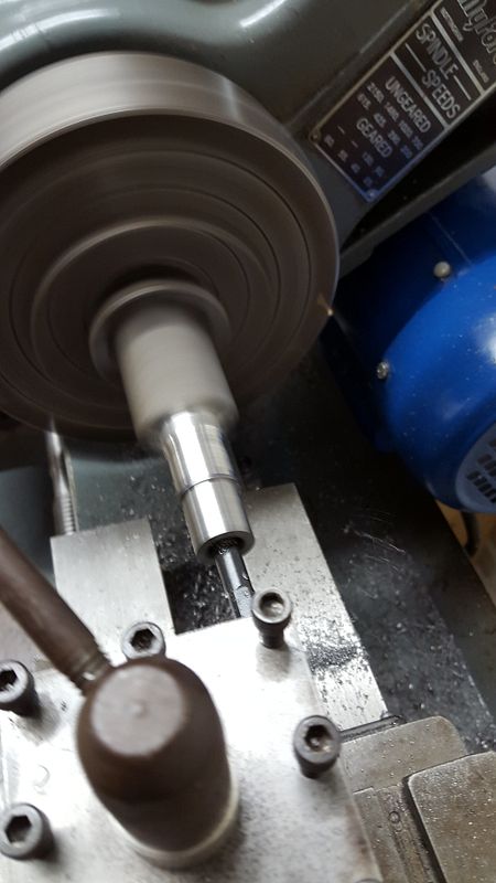
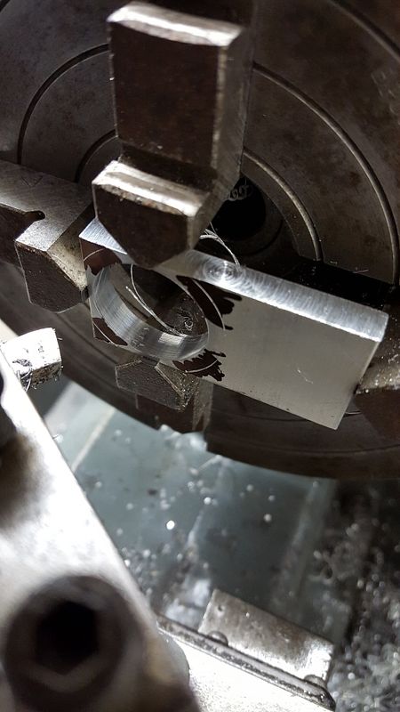
First time boring in the lathe!
2015-11-05%2022.27.59.jpg


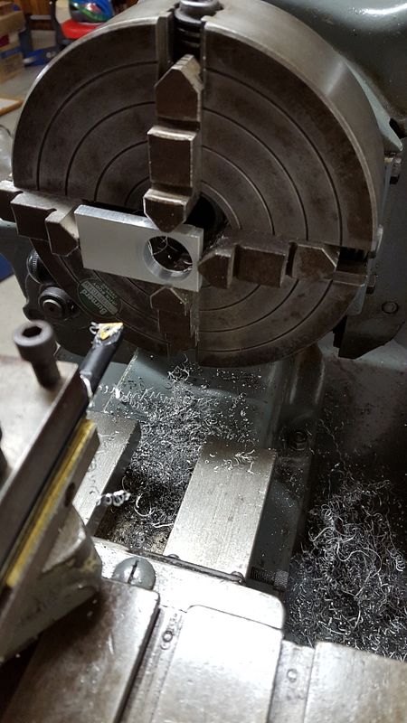
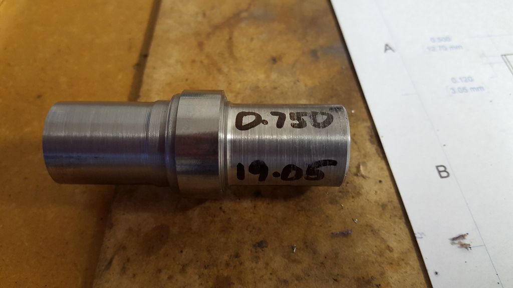
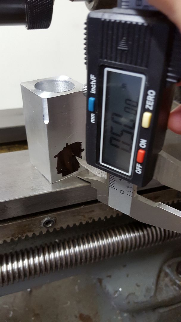
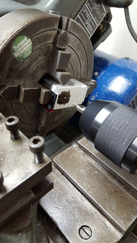
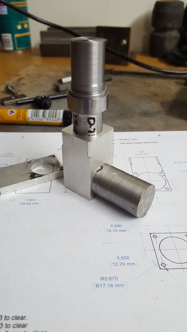
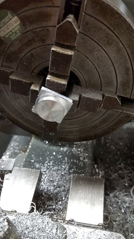
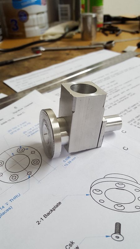
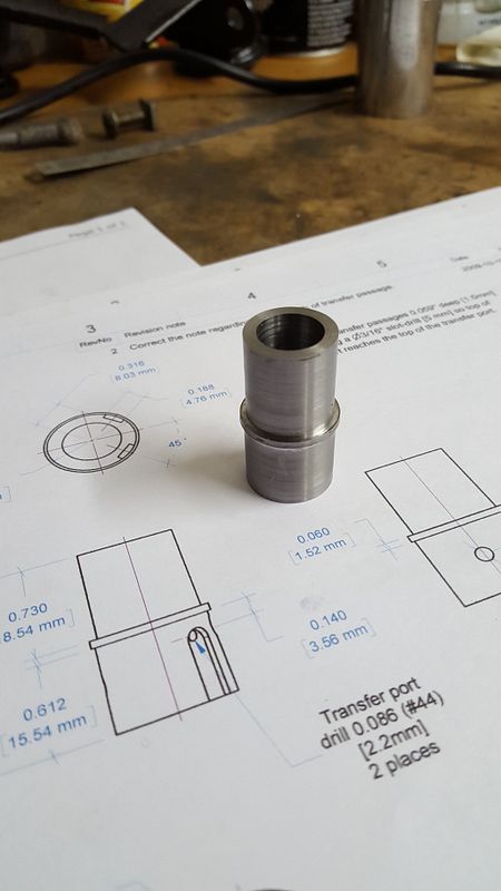
Testing with the hole gauge
2015-11-05%2022.33.11.jpg


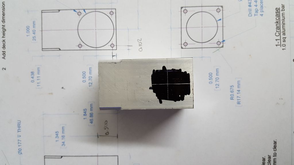
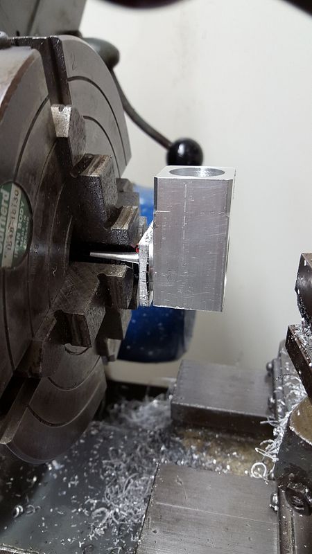
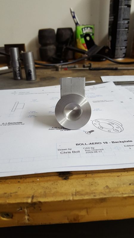
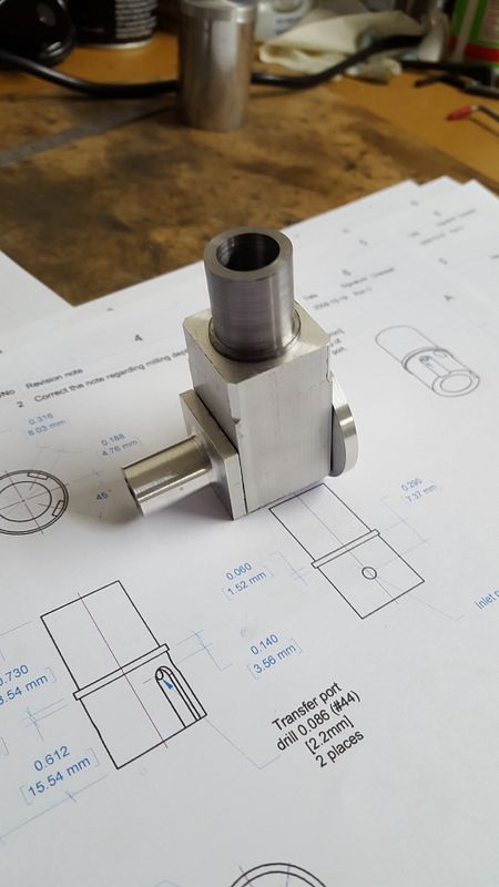
I used the point of the knife tool to scribe the PCD to locate the mounting holes on
2015-11-05%2022.39.55.jpg


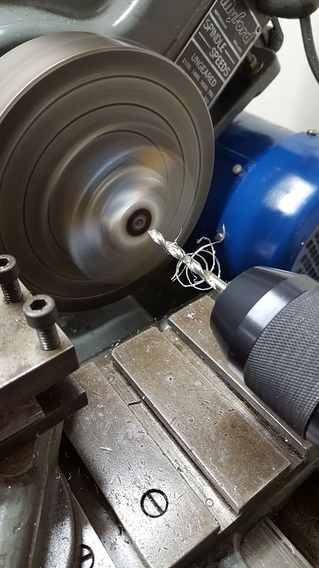
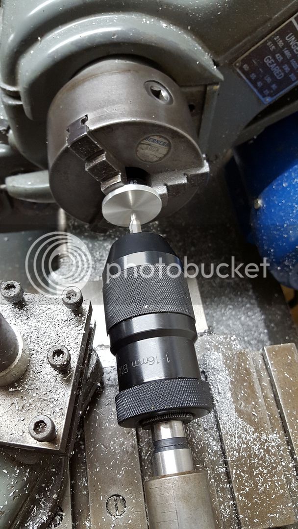
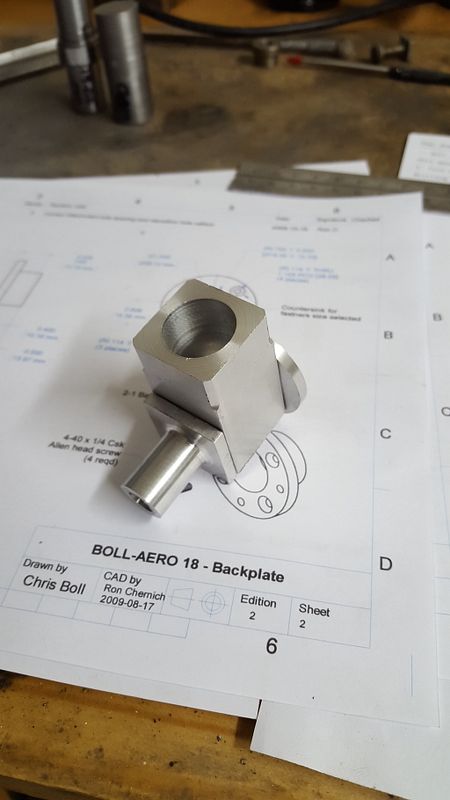
And this is where I finished for the evening
2015-11-05%2022.49.56.jpg


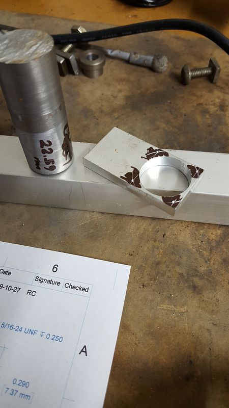
So I just have drill the mounting holes in the jig tapping size so that I can spot drill through it later.

I am going to remake the hole gauge as I screwed up and overshot so that it is now 0.02mm undersize and so is a bit loose in the hole in the drilling jig. According to my digital calipers that is the correct bore size.

Next up the crankcase.
 
Roboguy,

Congratulations, the BollAero is a wonderful engine to start with. I too made that as my first engine and there has been a few more since then.

If you don't have a good Mill, then marking out is crucial and one trick I have learned is to use a simple sewing needle, put it in a drill and as the drill rotates bring the point up to a grinding wheel. In moments you will have the sharpest needle ever, even slightly blued on the end, but when used for marking out in alloy, you can get an accuracy down to almost a thou.

When it comes to your piston and bore fit, I will help you with the process I learned from David Owen, a process that almost guarantees great compression, the secret to a good diesel.

I will watch with interest your progress ... Ed
 
Great start to a great engine. Looking forward to next instalment
 
Off and running! Don't worry about the exact dimensions all the time.
Many of the mating fits will be adjusted to fit as you go. If you make the
bore, for example, .05mm to big then you make the piston bigger to fit.
Those little adjustments we can do when building one-offs and no one
is the wiser except you. And us if you tell us! :rolleyes:

Keep on goin'.

Pete
 
Thanks very much for the encouragement everyone!

Ed, I'm definitely interested in any tips for the piston and bore fit. Several others have pointed out this will be one of the most critical aspects of the engine.

Apologies if I show stuff most others would skip out. Before I started I looked around for a Boll Aero build thread and couldn't find much, so I'm hoping that if I do a decent job of documenting my own progress it might be useful to others - especially first time builders like me.

Also, apologies for the mixing of units between imperial and metric! I am working from imperial drawings with an imperial lathe, but all my measuring equipment is metric and being from New Zealand metric are my "native" units.

So, some more progress has been made!

I started by cutting some 1" square aluminium to length + a few mm to allow for squaring up the ends. I then chucked this up in the four jaw and faced the first end.

2015-11-07%2015.04.18.jpg


Next, I removed it from the chuck, marked out the exact length 46.86mm (1.845"). I also marked of the amount to chamfer on the top corners of the crankcase. Back in the four jaw this time with some alloy shims (made from an old coke can) to protect the work piece. I used my tool post mounted DTI to ensure that the work piece was exactly centred.

2015-11-07%2018.33.20.jpg


Setting things up in the four jaw chuck isn't anywhere near as difficult as I had feared. It requires a bit of faffing about, but I plan to make a second chuck key in the near future and that should speed things up.

I centre drilled and supported the work piece with a live centre while I chamfered the corners. The tail stock centre probably wasn't required, but due to the interrupted cuts that were going to be required to chamfer the corners I thought it prudent to provide some extra support to avoid the work piece slipping out of centre.

Finally I enlarged the central bore using a succession of drills ready for the boring bar.

2015-11-07%2019.01.05.jpg


And that's where I finished for the day, ready to bore to size for the cylinder.
 
OK Roboguy,

Here is my BollAero .. about a couple of hours running now on 2nd piston/cylinder combination after David Owen showed my me how to get a great fit with these components. Video is of one stopping and restart with 1 flick - did this 10 consecutive times ! A wonderful first engine to build .. here running a 10 x 4 wood Turnigy prop at around 5300rpm

[ame]https://www.youtube.com/watch?v=GGVX159QPr4&feature=youtu.be[/ame]
 
Awesome, thanks for posting this. That certainly gives me something to aim for!

It's very humbling when you start building your first engine. So many of the things that other people make look so simple are suddenly quite a challenge, and even just figuring out how to start is difficult sometimes.
 
Over the last couple of evenings I've managed to make some more progress. The next step was to bore out the crank case for the cylinder. Before doing that though I realised I should have made a hole gauge for that bore as well. I don't currently have an inside micrometer or telescopic gauge, so a hole gauge that has been turned to exact size is the next best thing.

To avoid messing up my nicely centred crankcase I simply removed the four jaw chuck with the work piece in situ. I then chucked up a bit of scrap in the three jaw and turned it to exactly 0.750" (19.05mm). No mistakes this time and I got it bang on.

2015-11-08%2020.12.34.jpg


I then replaced the four jaw and bored the crankcase for the cylinder. I managed to get a very nice tight fit on my hole gauge, and my digital calipers tell me it's exactly 0.750 :D

2015-11-08%2020.05.09.jpg


2015-11-08%2020.10.58.jpg


The next task to complete the major work on the crankcase was to bore the through hole for the main bearing and back plate to locate into. I don't have a height gauge at the moment (must get one of those but so expensive!), so I improvised and using the lathe bed as a surface plate and my digital callipers as a poor mans height gauge I marked out the centre.

2015-11-09%2020.08.59.jpg


2015-11-09%2020.09.54.jpg


Back in the four jaw, I used the tail stock centre as a guide to get the crank case close to centred on the punched point.

2015-11-09%2020.22.47.jpg


To fine adjust the position I used my shop made tool post wobbler. It appeared to be pretty much bang on with no movement after some adjustments.

2015-11-09%2020.25.22.jpg


Then I centre drilled, and used a succession of drills to take the hole size out to 12mm.

2015-11-09%2020.35.16.jpg


2015-11-09%2021.22.32.jpg


2015-11-09%2021.37.19.jpg


Looks like I forgot to take a photo of the boring process again! I think it's because I found that part quite stressful. This is the first part I've done any boring on and I was taking very slow to ensure I didn't overshoot.

It still needs some cleaning up and some holes drilled and tapped, but here is the mostly finished crank case.

2015-11-09%2023.06.40.jpg


2015-11-09%2023.02.01.jpg


Here's where I own up - somewhere along the way I've screwed up and the through bore is off centre to the left by about 0.010". I'm not quite sure how it happened, but I guess the only reasonable explanation is that the rubber in my wobbler is too hard and I couldn't tell that the work piece was still fractionally off centre.

Does the 0.010" off centre mean I need to scrap the part and start again? Or do people think I can get away with it?

I appreciate all the encouragement and advice you guys bring. If you see me doing something stupid, or if there's a better way to do something please let me know!

Next I'll either do the main bearing (front part), or the back plate. I don't suppose it matters which I do first.

Cheers,
James
 
I think the two bores not being on center by that much is not going to let the engine make a full revolution. I think you are going to have to remake the part. But, it will be easier this time.
 
Roboguy, just had a look at the drawings - 10 thou off centre will be ok in my opinion. You might have to relieve a tiny bit of the inner sidewall bottom of cylinder one side of crankcase for conrod clearance, but this is normal in most engines anyway.

Make sure you mark out front and back bolt holes off the tunnel not the crankcase sides - or better use those components as the template initially only drilling tapping size in them.

If you make two opposing sides 10 thou wider - the dreaded file will aesthetically fix the visual problem and no one will ever know !

Try my sharpened needle for marking out on a scrap and see how fine the scratch is and thereby how accurate you can get with it ....good luck - and welcome to the world of subtle changes .... Ed
Hi Ed,

I had already realised that drilling the crank case mounting holes was going to be a challenge without the ability to do coordinate drilling (no mill), so that was why I made the drilling jig as my first step. I've drilled the jig tapping size, so hopefully it should allow me to get everything to line up.

I've been dwelling on how I ended up with the crank bore so far off centre and on the way to work this morning it dawned on me. I am using 1" stock, but of course I made an amateur mistake and forgot that 1" stock isn't exactly 1"! I measured it tonight and sure enough, it's 1.008, so there is the best part of my extra 10 thou. Basic error, and one I don't plan to make again!

Started work on the main bearing tonight but haven't made much progress.

Cheers,
James
 
I think the two bores not being on center by that much is not going to let the engine make a full revolution. I think you are going to have to remake the part. But, it will be easier this time.
Thanks for the feedback. I am going to forge ahead for now and see how things fit together once I've got the main parts made up. I've prepared another crank case blank, so if it's not looking good I'll remake it.

Cheers, James
 
Where can I find the plans for this engine.
Kind regards Matt
 
Well I've managed to make some good progress over the last few evenings and now have the front bearing and back plate done (with the exception of the crank case screw holes).

I started with the main bearing. I cut a length of 1" square aluminium and faced it up, then marked out the centre, and the length to turn down at the front. Then I chucked it up in the four jaw and used the tail stock centre as a guide to get it roughly centred up.

2015-11-12%2020.30.56.jpg


I then turned it down to exact diameter and length and used a round nosed tool to produce the fillet in the corner between the mounting flange face and the bearing.

2015-11-12%2021.46.44.jpg


Back in the four jaw chuck with shim to protect the just turned surface, it was trued up and the spigot that will locate into the crankcase was turned with repeated testing for a very tight fit.

2015-11-12%2021.59.32.jpg


2015-11-12%2022.44.14.jpg


2015-11-12%2022.44.40.jpg


Once the spigot was finished, the hole for the crank was drilled out to 7.7mm (0.303") ready for reaming with a 5/16 reamer.

2015-11-14%2021.13.59.jpg


And that is the main bearing completed with the exception of the holes for the crankcase screws.

2015-11-14%2021.22.28.jpg


2015-11-14%2021.23.13.jpg


2015-11-14%2021.23.28.jpg


2015-11-14%2021.23.53.jpg


With the main bearing completed the next job was the backplate. I cut a length of 1.5" aluminium to length, plus enough for the cylinder head and a chucking allowance. I then chucked this up in the three jaw and faced the end and tidied up the outer diameter for a short length.

2015-11-14%2022.00.11.jpg


I then marked out the 0.400" to turn down for the spigot that will locate into the back of the crank case and proceeded to turn that down to 0.890", repeatedly test fitting with the crankcase as I got close to the final diameter.

2015-11-14%2022.06.46.jpg


2015-11-14%2022.14.03.jpg


2015-11-14%2022.20.01.jpg


2015-11-14%2022.34.09.jpg


2015-11-14%2022.34.13.jpg


Happy with the fit I reversed the backplate, protected the turned spigot with some shim and rechucked it in the three jaw. I then faced it to length - exactly 0.150".

2015-11-14%2022.44.42.jpg


The next step I was a bit nervous about. It is a blind bore that leaves quite a thin wall so I didn't want to overshoot in any direction and push through. It's also the first time I had done a blind bore so there was that aspect to figure out as well.

2015-11-14%2022.45.43.jpg


2015-11-14%2023.01.54.jpg


2015-11-14%2023.21.10.jpg


2015-11-14%2023.23.10.jpg


2015-11-14%2023.23.24.jpg


2015-11-14%2023.23.30.jpg


Next up the cylinder I think...
 
I've made a bit of progress with the cylinder. I ended up making it from 1" square stock as that is the only size I had to hand of suitable material. Next week I plan to visit the metal suppliers and pick up some more stock for this and other projects. I had a piece of steel already cut which was a longer than necessary, but I decided to just go with it to avoid wastage.

I started by turning the required length down to the largest O.D. of 0.800". I then made a mistake, which if I had taken the time to think the machining sequence through more carefully would have been easily avoided. I turned the end of the piece down to 0.700" which is the O.D. of the top part of the cylinder. I should have turned the 0.750" for the bottom part so that I could test fit it in the crank case to ensure I got a tight fit. I ended up turning the 0.750 without being able to trial fit and as a result it is probably about 1 thou undersize, but it's not sloppy in the crankcase so I think it will be fine.

I then bored the cylinder 0.500" right through and parted it off. I then re-chucked it in the three jaw chuck and faced the bottom end to length.

2015-11-23%2022.02.47.jpg


2015-11-24%2022.42.04.jpg


2015-11-24%2023.00.56.jpg


2015-11-24%2023.01.07.jpg


I'm now in the process of drilling the various ports and milling the transfer passages.

Couple of questions:
1. I've read about using lapping paste to lap the piston to the cylinder. Do people use diamond lapping paste for this and if so what grade / micron size?
2. What size prop should I be using with this engine?

Cheers!
James
 

Latest posts

Back
Top