Boll Aero - my first engine build

Home Model Engine Machinist Forum

Help Support Home Model Engine Machinist Forum:

This site may earn a commission from merchant affiliate links, including eBay, Amazon, and others.
James,

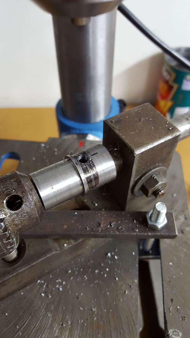
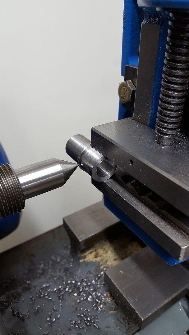
The process I use that I was taught to me by David Owen and is in fact on his Owen Mate plans. For the cylinder you make a simple lap and use diamond paste to lap the inside of the bore.

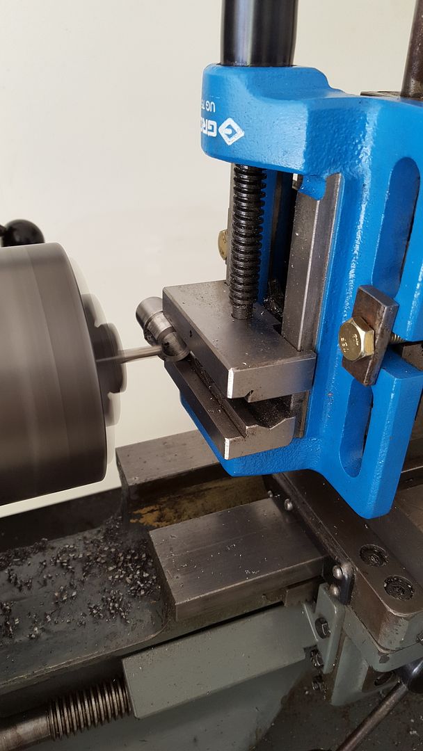
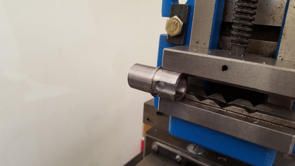
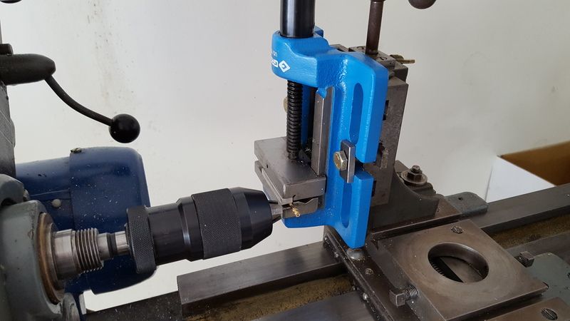
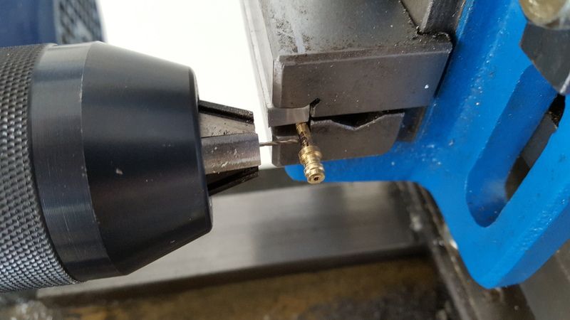
The lap is machined to about a thou undersize then a blind hole is drilled and tapped one end. A hacksaw cut then divides it and a screw or grub screw wound into the tapped hole. Mount the lap in the lathe at a slowish speed and manually run the cylinder up and down with some fine paste on it. Make sure you cover your lathe and everything around it as the paste will work nicely on all the mechanical parts wearing them out super fast ! The deeper you go with the screw the more it expands to lap the inside of the bore to a fine finish and also the internal shape you need which is ever so fine a taper to the top. You are looking to have a 1 or 2 tenths of a thou taper at the top from the ports - to actually pinch the piston tight there, but not so tight at the bottom of the stroke.

I then - until recently - (I bought a internal bore gauge) used that lap to measure the internal diameter of the bore and to make the piston to that size. By expanding or contracting the screw you can get an extremely accurate feel as to the taper and size that way. Make sure you scrupulously clean the lap first though - I use carby cleaner. It is a good idea to buy a sonic cleaner - they aren't expensive and do a remarkable job of cleaning with degreaser as the fluid.

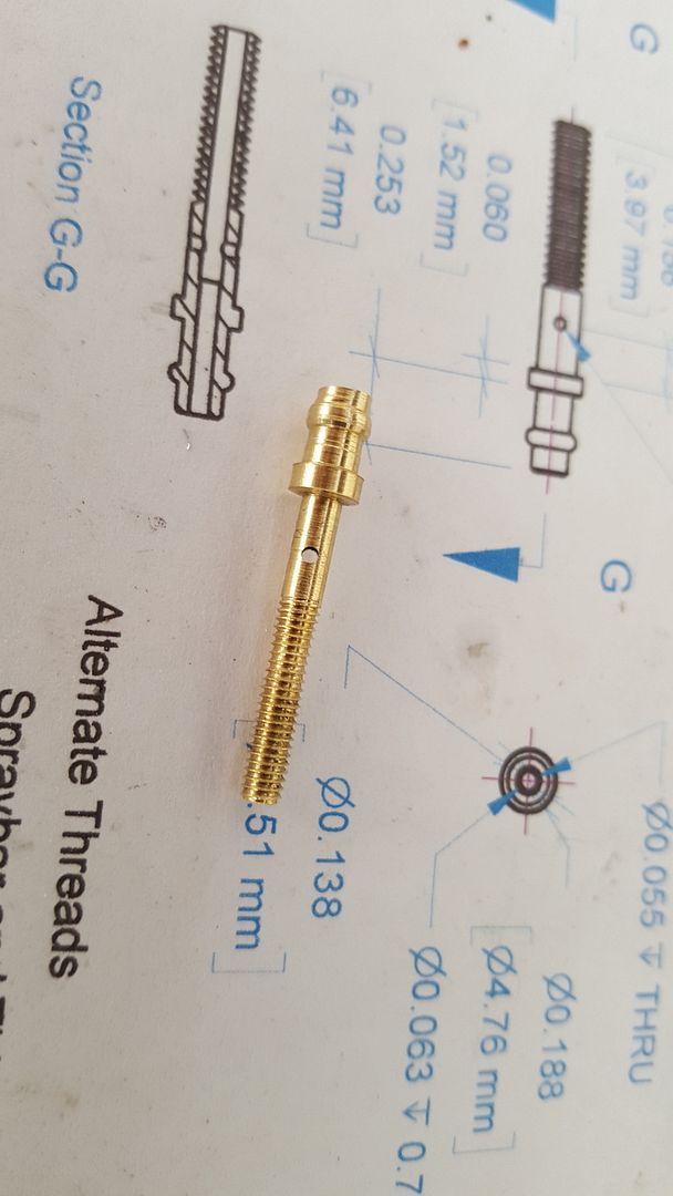
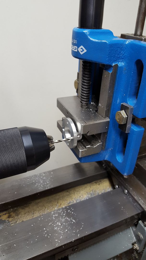
I then make the piston exactly to the top of the bore size plus a zillionth - First I make it about 1/2 a thou oversize then use a flat (a ruler works well) with some fine wet and dry to linish the piston down to a size. All pistons have an internal hole and I have found making a scrap piece of alloy rod that size and pushing the piston on has enough holding power to be able to do this. No superglue etc needed. When I get very close I then make the gudgeon pin holes which will put the piston slightly out of shape and again using the wet and dry against a flat linish the piston exact. Sometimes the gudgeon will force the piston a bit out of shape again so I install it through the scrap alloy mounting rod noting ever so carefully which way it went in and forever that is the way it goes in and out.

The aim is to have the piston so tight at the top of the stroke it squeaks - and most times it will only go 3/4 way up the bore when first assembled. A bit of oil and turning back and forth with a propeller usually beds it all together. Occasionally I have made it too tight and have to disassemble and linish the piston a bit more, better this than to have the piston too slack. It is truly amazing how tight a piston can be in the bore yet the engine will start and run beautifully - and the secret of a good diesel is good compression.

I know this sounds complicated - but really it isn't, and I can tell you it sure beats making several piston/cylinder combos in the hope that one will work !

Keep up the great work .... Ed
 
Thanks very much for that detailed explanation Ed!

That certainly gives me a very good idea as to how to complete that critical step.

Novice question - how critical is the width of the transfer passages in these engines? Reason I ask is that I was just about to mill these and realised the plans call for a 5mm slot drill, and the smallest I have is 6mm. Do I need to hold off and order a smaller bit, or would a 6mm suffice?

Cheers,
James
 
6mm v 5mm is a 20% increase which will slow the gas passage down a bit - but in imho I don't think it will matter one iota, the engine is not a fire breathing hodrod, where such things will affect performance.

In fact I've just looked at the plans again and the inlet holes determine the gas flow, so 5 v 6 mm will make zero difference. ..... Ed
 
To check the piston/cylinder tolerance is correct: Dry piston/cylinder ---> The piston feel tight into the bottom of cylinder. Oiled piston/cylinder ---> The piston feel loose in bottom of cylinder and more and more tight on way to top of the cylinder. The cylinder/piston must be dull grey (a lot of oil pockets in surface) after lapping is done, also not mirror finished surface.

It is important the cylinder will expanding to "parallel cylinder" and keep compression under running. If the cylinder was parallel then the cylinder will expanding to loose compression and, the engine will stop when engine is up to working temperature.
 
6mm v 5mm is a 20% increase which will slow the gas passage down a bit - but in imho I don't think it will matter one iota, the engine is not a fire breathing hodrod, where such things will affect performance.

In fact I've just looked at the plans again and the inlet holes determine the gas flow, so 5 v 6 mm will make zero difference. ..... Ed

Thanks for the reply Ed. I've taken a gamble and used the 6mm - I've also ordered a 2/3/5mm endmill pack of ebay today so I can always remake the cylinder if this one doesn't work out.

I've made some more progress this weekend but have run out of time to post an update tonight.
 
The next step was to drill the various ports in the cylinder and mill the transfer passages. Because I don't have a mill yet I am doing all my milling operations in the lathe on the vertical slide. I used a dead centre in the headstock spindle to assist with lining up the end mill over the transfer port.

Before the chorus of "you shouldn't be using chuck to hold a milling cutter" - I know. An ER32 collet chuck and set is on my Xmas wish list!

2015-11-25%2022.47.22.jpg


2015-11-26%2022.27.48.jpg


2015-11-28%2016.14.31.jpg


2015-11-28%2016.15.21.jpg


2015-11-28%2016.33.54.jpg


For a change I decided to start working on some of the fuel system parts next. The venturi is the obvious place to start. The plans suggested making this part from 5/16" square aluminium, but I didn't have any. So I turned down some aluminium round to 0.313" for 0.500", then 0.443" for 0.250", and finally back to 0.313" for the final 0.250". The 0.443" is the width across the diagonal of a 5/16" square bar, which left it the right diameter for me to then mill it square in the shop made dividing attachment that I got with my lathe. I then cut a 5/16-22 BSF thread instead of the 5/16-24 UNF thread specified as I don't have any UNF tap and die sets.

2015-11-28%2017.32.43.jpg


2015-11-29%2012.06.34.jpg


2015-11-29%2012.14.11.jpg


2015-11-29%2012.34.20.jpg
 
Not using a chuck to hold a milling cutter relates to a Jacobs chuck (drill chuck) as they cannot withstand the size loads of milling and dangerous things can happen. Your lathe chuck should be more than up to the task of milling work I would think.
 
Hi all,

I've not had much time to work on the engine over the last week or so - lots of end of year Christmas functions and family commitments!

I have made a little progress though. Firstly I machined up a couple of Jam nuts that fasten the venturi body to the crankcase. These I machined from some scrap round brass I had in my junk box. I turned them to diameter, drilled and tapped 1/4-22 TPI BSF as I have a good quality set of BSF taps. I then used my shop made dividing head to mill the hex nut flats, and finally parted the nuts off in the lathe. I forgot to take photos of the process, but here are the finished products.

2015-12-06%2010.45.50.jpg


After test fitting the venturi body in the hex nuts I felt the thread was a bit sloppy. I'd not set the split die far enough apart and had over-cut the thread on the venturi so I decided to remake it. Once done I drilled and tapped the crankcase, and also drilled the exhaust port in the crankcase while I was at it.

2015-12-09%2021.22.38.jpg


The next part I decided to tackle was the cylinder head. I faced up a suitable length of 1.5" aluminium in the three jaw and turned it to diameter. I then drilled and bored the 0.700" hole for the cylinder. I clearly need a bit more practice with the boring bar as I had it almost exactly to size with the cylinder just about fitting in. I probably needed to take 0.001" off, but managed to overshoot and now the hole is one or two thou to big. I'm going to remake the cylinder anyway as it is also a bit loose in the crankcase, and I now have a smaller end mill to mill the transfer ports the correct size.

2015-12-09%2021.31.37.jpg


2015-12-13%2015.54.57.jpg


I'm about ready to turn the fins now. I ground a HSS tool almost exactly to size. It's 0.145" wide, and the space between fins is supposed to be 0.150" according to the plan.

2015-12-13%2015.55.26.jpg


Slowly making progress...
 
Christmas, summer camping holidays and other activities have slowed me down over the last few weeks, however I have finally managed to make some more progress on my engine.

Turning the fins with my specially ground tool worked reasonably well. The square end left a bit of chatter but I'm willing to live with it. This engine is definitely all a learning experience for me at this stage so getting a perfect finish on each part is just not realistic. So, after creating a small mountain of swarf on the lathe I had a pretty good looking cylinder head, and that's when I made my mistake. When parting off I didn't support the part, and it bounced back under the chuck which gave it a decent whack, gouging the bottom fin and bending it back upward toward the fin above.

Question: how do people normally support a part like this when parting off to ensure this sort of thing doesn't happen?

2015-12-16%2021.42.21.jpg


2015-12-16%2021.42.28.jpg


2015-12-16%2021.56.45.jpg


2015-12-16%2021.57.04.jpg


After I got done wailing and gnashing my teeth for a bit, I straightened it the fin out and took a skim of the circumference of the whole cylinder head. The bottom fin is still not quite straight and has a great gouge in the bottom but I'm going to push on for now otherwise this engine will never run!

I had ordered some fasteners and some nice metric spiral taps before Christmas and they had arrived, so I decided it was time to drill and tap the crankcase. I used a drilling jig I had made earlier to first drill the main bearing and the backplate, then the plan was to drill through these to ensure the holes all lined up. That's when I made my second stupid mistake!

While drilling the first hole in the crankcase, I managed to break the 2.5mm drill bit I was using. I think I probably tried to go to fast and the bit caught on the edge of the existing hole in the main bearing part I was drilling through as it was biting into the crankcase material. The shear would have been enough to snap the small bit.

Lot's of bad words ensued and I took a break for a day.

Then I remade the crankcase, and this time managed to get a really nice fit for the cylinder, and then went straight into drilling and tapping again. This time round I spotted through the main bearing holes, then removed the part and drilled the crankcase holes on their own. I took it nice and slow, making sure to retract the bit and allow the swarf to clear every now and then. Probably not necessary considering I was only drilling 0.250" deep holes, but I really didn't want to be making a third crankcase!

Spotting through the fins on the cylinder head had me holding my breath, but it all went well and I now have the crankcase all drilled and tapped.

2015-12-30%2013.23.41.jpg


2016-01-01%2010.46.10.jpg


The image above also shows the finished tommy bar. The plans suggest 1/8" music wire, but I didn't haven any to hand so just turned down some 10mm diameter 1215 steel I have nearly 4 meters of.

Yesterday evening I made the compression screw. This was a pretty simple turning job apart from the thread. The plans call for a 1/4-32 UNF thread, but I don't have any UNF taps or dies, so I decided to make this a metric thread. I went with 6mm x 1.0 which is a slightly coarser thread (at approximately 25 TPI), but I figure that should be fine enough adjustment. The next challenge of course is cutting a metric thread on a older imperial lathe. My Myford Super 7 has a quick change gearbox, and by changing the final gear on the tumbler assembly to either a 33 or 34 tooth gear you can get very close approximations to most metric pitches (Harold Hall has a handy reference table here http://www.homews.co.uk/page346.html). So, using a 34 tooth final tumbler gear I cut my 6mm x 1.0 thread, and then finished it off with a die. All that remains to finish this part is to cross drill the compression screw and press in the tommy bar.

20160106_230601.jpg


I'm debating with myself what to tackle next. I'm wavering between finishing off the last remaining parts for the fuel system, or moving on to the crankshaft...
 
For tiny stuff that tends to disappear on parting I normally place a rag under it just before parting. Of course I make sure I'm never touching the rag while the lathe is running.
 
If I understand correct, both the chattering & sudden part might be related to the relatively wide parting tool plus it being a rectangular section. It might be better to try:
- a thinner width blade
- slight angle (viewed from top) so it parts through at a thin line vs. thick line
- with gummy aluminum, razor sharp stoned edge seems to work for me
- a dowel from the tailstock protruding into center of part to catch the work when parting occurs, keep your fingers out of there
- all the normal other parting tricks, centered tool, perpendicular blade, slower rpm/feed, cutting fluid...

Some thin walled stuff of certain alloys can just be a plain bugger. Sometimes I resort to partial parting & then finish the cut with a jeweler saw just to be safe. You would then need to finish the edge of course. Personally I try not to trust a parting tool for hitting the length in one shot at the best of times. Good luck
 
Firstly thanks to Petertha, Cogsy and 10K Pete for your replies to my parting off question.

For the record, the parting off tool I am using is a standard Eclipse thin blade tool for Myford lathes. You can actually see it in the background in a couple of the photos below.

Over the past few days I have made some progress on the rest of the parts for the fuel system. I've just got to finish remaking the Venturi (for the third time!), as I need to make hole for the spray bar smaller. I ended up making the spray bar slightly smaller than the plans call far as I had to use a 6BA thread as I didn't have taps and dies for either the 6-32 UNC the plan uses or the 3.5Mx0.6 metric alternative.

Anyway, here's some progress pics. Hopefully the next lot will have the fuel system finished and in place on the crankcase, and I'll finally be ready to start work on the crankshaft.

2016-01-07%2020.18.23.jpg


2016-01-07%2013.54.02.jpg


2016-01-07%2013.54.07.jpg


2016-01-09%2021.03.33.jpg


2016-01-07%2015.42.18.jpg


2016-01-07%2020.12.44.jpg


2016-01-09%2022.12.23.jpg


2016-01-09%2023.02.16.jpg
 
Hi guys,

I'm glad people are finding this interesting! I realise it's a pretty simple build compared with all the other masterpieces I am following on this forum at the moment, but everyone's gotta start somewhere right?!

Following along and this build has inspired me to make this my first engine also!
Lane

Hey Lane, thanks for following - it's been pretty achievable even for a complete novice like me thus far. However I am about to start tackling the hard parts. As everyone has already pointed out the tough part will be getting the compression right with a good piston / cylinder fit.

Cheers,
James
 
So I got a little time in the workshop last night and managed to finish of all the fuel system parts apart from the needle as I need to get some 1/16 music wire for that.

I milled the square section on the replacement venturi and then cross drilled 2.8mm for the correct fit from my slightly narrower spray bar. As per my earlier efforts I used the vertical slide and my shop made dividing attachment for the milling.

2016-01-13%2008.59.37.jpg


2016-01-13%2008.59.54.jpg


While I had the dividing attachment set up I also milled a short length of brass I had previous turned down, drilled and tapped in order to make a 6BA nut for the spray bar. Here's the finished product.

2016-01-11%2022.43.55.jpg


Next job on the list was to cross drill the spray bar. This required drilling a 1mm hole through a 2.8mm brass tube. That's tricky given my experience level and the tools I have at my disposal. I've not had any luck drilling anything accurately with my budget drill press, so decided to do this on the lathe as well. This way I could accurately position the work piece. It worked out quite well as you can see.

2016-01-13%2014.15.27.jpg


2016-01-13%2014.15.22-1.jpg


2016-01-13%2014.22.28.jpg


The final job for the night was going to be adding the counter sinks in the back plate. Boosted by my previous success drilling in the lathe I decided to continue with that approach. I should have heeded the warning voice in the back of my mind that said "that counter sink bit looks an awful lot like a milling cutter...". Naturally on the second hole the Morse taper gave up and the drill chuck spun loose. Luckily not too much damage was done, but one of the holes is a bit wobbly. I swapped the drill chuck out for the lathe chuck which solved the problem. I used a 3mm drill bit to centre the work piece before switching to the milling cutter. It worked well other than the fact that it has highlighted to me how knackered my old 3 jaw chuck is - the run out on that is awful!

2016-01-13%2022.43.27.jpg


2016-01-13%2022.32.54.jpg


2016-01-13%2022.59.56.jpg


2016-01-13%2023.06.49-1.jpg


2016-01-13%2023.14.51.jpg


2016-01-13%2022.06.01.jpg


2016-01-13%2022.06.21.jpg


Next up I am going to tackle the crank shaft. The plans call for the crank to be made as three separate parts using a machine screw for the threaded section, and a crank pin made from drill rod. Instead I plan to make the crank as single one piece unit. I'm going to try cutting the M4x0.7 thread on the lathe, and turn the crank pin as an eccentric turn using the four jaw chuck.

Righto - it's off to the workshop I go!
 
This morning I managed to get a couple of hours in the workshop and the first thing I wanted to do was check I could cut a M4x0.7 thread reliably. I'm using a bit of an approximation where the 24 tooth tumbler gear and the 36 TPI position on my gearbox works out to a pitch of about 0.69 which is not too bad.

I turned some 10mm 1215 down to 4mm and then using a 60 degree single point HSS tool I had ground, I tested how well I could cut the thread. The first attempt was pretty shabby. I was reversing the gearbox to return to the beginning each time as you can't disengage the half nuts when cutting a non-native thread (i.e. metric on an imperial lead screw). Obviously there is enough backlash / slippage in the gear train / gearbox when changing direction that the pickup on the thread wasn't reliable and the result was a bit of a mess.

After giving it a little thought I decided to try switching the motor direction instead and run the lathe in reverse to get back to the start each time. This worked much better, although it is a bit laborious as I have to wait for the motor to completely spin down before changing direction. The finished thread is sharp and an off the shelf M4 nut threads on and off beautifully.

I now feel ready to start on the crank shaft. I've cut a 3" length of 1045 steel and am ready to go.

2016-01-15%2010.46.45.jpg


2016-01-15%2010.47.33.jpg


2016-01-15%2010.47.44.jpg


2016-01-15%2010.48.23_1.jpg


2016-01-15%2010.52.38.jpg
 
Great progress so far , been watching with interest , the only thing i would have done differently is to skim up the main block surfaces to be square and flat because as you found stock material is not to size , and frequently neither is it square or flat , which can cause problems with covers and bearing housings not seating and sealing properly , still hopefully this motor will run and you will know better on the next project.
regards Geoff
 
Hallo,

I have followed your work the making from a Boll Aero 1.8 model diesel engine.I made several Boll model engines myself,but after following your thread as well i must really say perfect done man and very great craftmanship it all fits and it all works fantastic.My gratulations for such a nice made and well running model diesel motor.At the moment i just finished the Boll 49 8,02 cc model glow engine.I hope that it will start and run at least.

Lots of sucess with your great metal working hobby.

modelmotor-Europe.
 

Latest posts

Back
Top