Best way to mill this piece

Home Model Engine Machinist Forum

Help Support Home Model Engine Machinist Forum:

This site may earn a commission from merchant affiliate links, including eBay, Amazon, and others.

JMI

Well-Known Member
Joined
May 22, 2008
Messages
134
Reaction score
0
Location
Seattle, WA
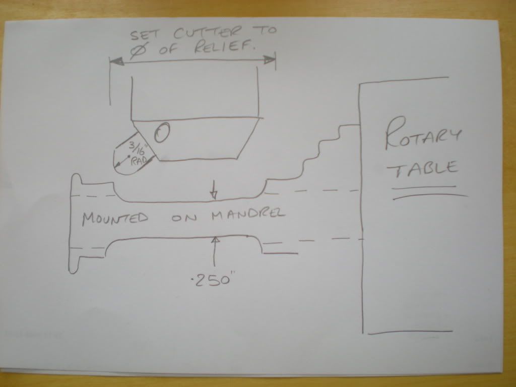
Have made this piece in 303 stainless up to the point where the next step is to cut the reliefs on both sides with the .187 radius also.

crosshead_crop.jpg


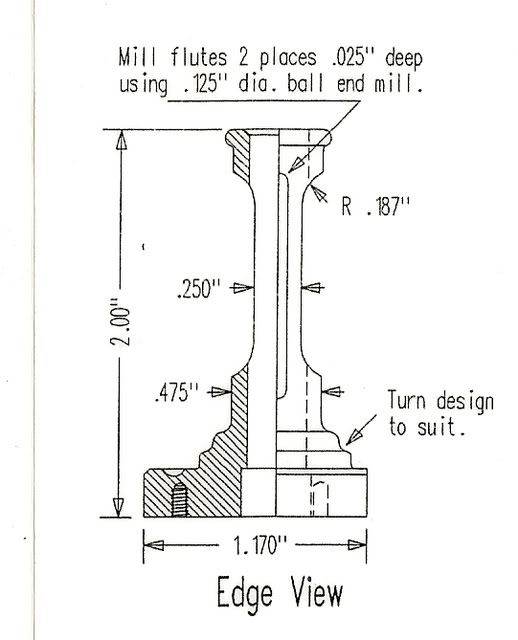
So I can use a 3/8" end mill and use the side of the cutter to achieve the approximately .112 depth and also the .187 radius on the end of the cut.
Is there a better/different way. Say using the end of a regular/flat end mill to remove the bulk of metal and than use the end of a different cutter (ball type? 3/8"?) to get the .187 radius?

Is this sounding as clear as mud?

TIA

Jim
 
Hi,
It would appear that you will need to be set up to mill the flute with a ball end mill. With the same set up you could do the side cuts with a 3/8 end mill as you stated.

How fussy is the radius? Does it need to be 3 decimal places or is it decorative and just needs a nice finish? ( looks like an engine column)

Dave

you might want to consider putting this on an indexer, I assume it's round?
 
I think it is a cross head guide. The radii look to me to be purely decorative.
 
I just used the side of a 3/8" endmill, the part was clamped the the longway from end-to-end in the vise. I got by with it on both of my Mizers. Make sure to not get them 90degrees off from the flat milled on the base end! This relief gives access to the set set screw on the crosshead. Not real fussy!
 
Allowing for Mike's caveats about alignment and access, this is an "if it looks right it is right" proposition, so don't sweat it too much. I don't recall just how I did it, but I assume I used the side of a 3/8" dia. end mill.
 
Thanks for the replies.
Yes, it is more of a decorative cut and certainly not critical.

There is/was a recent thread asking if forum members tried to work exactly to spec or if they allowed for large tolerances. I try (and occasionally succeed) machining to the drawing's specs. I figure if I can do it when it is not critical then nailing it when it is will be that much easier.

I suppose I will use the side of an end mill. I don't do a lot of removing of the machining marks cause they look decorative to me but I've never cared for machining marks that are left using the side of end mill.

Jim
 
Thanks to Mike N for the heads up on what it went to. Was wondering

Is that the little sterling that runs on a cup of coffee....seems very popular.

Dave
 
steamer said:
Thanks to Mike N for the heads up on what it went to. Was wondering
Is that the little sterling that runs on a cup of coffee....seems very popular.

Yes, it is Jerry Howell's Stirling "Miser".

http://www.jerry-howell.com/Miser.html

The attraction for me is it will run (I hope) almost anywhere with little energy input, sort'a like with batteries ;)

Jim
 
Thanks Jim,

Friend of mine made that full size and half size....both run nice
 
Hey Jim...post some pictures when you get the column cut! ;D

Im sure it will run fine!

Dave
 
I just finish mine recently, so here is what I did.

I used the side of the 3/8 mill to cut this with no trouble.

I actually turned the base and drilled/reamed the through bore on the lathe in the three jaw chuck.

Next, the part was held in a v-block and indicated in order to drill the mounting holes in the bottom of the part, the flat was cut as well.

I then turned a spud, mounted in a 5C collet, sized for a tight sliding fit and turned the narrow end of the column.

The spud was moved to the spindex and indicated in. I placed a straightedge on the flat and eyeballed it parallel (could have indicated it in) to a 1-2-3 block and cut the neck using the side of the mill. I left the flute off of my part, but it could be cut now. Notice that the other view shows that where the necking breaks through to the bore that the groove is opened to .25. The spindex makes it easy to do this in one set up.

It may not have been the best way to do it but it worked well for me.

Ken
 
To avoid the machining marks you talk of you could mount it on a tight fitting mandrel in a chuck on a rotary table.Set up a flycutter with a 0.1875" corner rad tool bit to cut what looks to be approx 1.25" diameter(no relief dimensions so am just scaling it)then just cut straight across to produce the relief in one pass.You would need to take it in small cuts to avoid overloading the setup but this way its all done in one pass.Then spin 180 degrees and repeat.

good luck Best Regards Steve C.
 
That flycutter idea sounds interesting.

Marinesteam, your moniker, have you worked off shore? I worked my first steamship (a T5 tanker) in 1973 as a wiper. Been in the maritime industry ever since.

Jim
 
Its all cosmetic. 20 minutes, you should be done.

dykem and a scriber to mark off the top and bottoms of the relief

clamp in mill vise, with the bottom of the column against the fixed jaw.

3/8 end mill to do the reliefs. Since they're just decorative, you don't need to be exact.

switch cutters and mill groove on top with ball end mill.

loosen vise, rotate part 180 degrees, using square to align. mill 2nd groove.

done.
 
scoop said:
To avoid the machining marks you talk of you could mount it on a tight fitting mandrel in a chuck on a rotary table.Set up a flycutter with a 0.1875" corner rad tool bit to cut what looks to be approx 1.25" diameter(no relief dimensions so am just scaling it)then just cut straight across to produce the relief in one pass.You would need to take it in small cuts to avoid overloading the setup but this way its all done in one pass.Then spin 180 degrees and repeat.

good luck Best Regards Steve C.

Doesn't a flycutter leave machining marks?
 
Yes a flycutter will leave machining marks but our man JMI did not care for the marks left by the side cutting of an end mill,and I personally do not like to try to blend the cut of an endmill into the corners of a slot that has rads cut by a ballnose cutter as it just looks wrong.What I meant was"a flycutter will not leave rough looking machining marks" but a nice smooth transition from flat into corner rad.

Best Regards Steve C.
 
The method I propose to use is drawn in this rather poor sketch below.
DSCN2394-1.jpg


Does it make sense to you now? This method is very handy to use as the width of the relief is set on the tool and you only have to just traverse across the job to the required depth.

Best Regards steve C.
 
Back
Top