Later in the text, John explains why he calls for drilling deep holes then tapping them-- to save on swapping out taps. You don't have to tap them all the way to the depth listed by any means.kvom said:This morning I attempted to machine an eccentric coupling fork. Unfortunately when I started to mill the slot I discovered that a 1/4" slot is too wide. It scales to .236. And in addition my 1/4" end mill is slightly oversize as well. So on to a redo with the 1/8" endmill. On the bright side I came to undestand that it's quicker to square off the stock for both forks at the same time and then cut them apart. :smart:
...
- He recommended that for tapping the drill rod for the crosshead guides, I should drill the hole with 1 or 2 sizes up on the drill bit and somewhat deeper. That will lessen the chance that I will break the tap (and I got a new tap to try it with).
...

You are using an out of date browser. It may not display this or other websites correctly.
You should upgrade or use an alternative browser.
You should upgrade or use an alternative browser.
Another Paddleducks Build
- Thread starter kvom
- Start date


Help Support Home Model Engine Machinist Forum:
This site may earn a commission from merchant affiliate
links, including eBay, Amazon, and others.
- Joined
- Jun 4, 2008
- Messages
- 3,285
- Reaction score
- 630
Shred,
Can you point to where the "adjusting screw" between the fork and the valve is described?
Can you point to where the "adjusting screw" between the fork and the valve is described?
- Joined
- Jun 4, 2008
- Messages
- 3,285
- Reaction score
- 630
I did some measurements and discovered that I indeed have enough brass for both the top and bottom plates, so as of now the only material I am missing, AFAIK, is the correct diameter drill rod for the spool valves.
My first task this morning was to cut the ~6"x3" bottom plate blank out of a 9x4 piece of 1/4" brass. I could have done this on the bandsaw, but decided to mill it out with a 1/8" endmill. It took longer, but in the end I wasted less material. From the cutoff, I then cut out a piece big enough to turn the disc for the 4th crankweb. My boo-boo was to crank it a little too hard and broke the endmill. Luckily it's a double ended mill, so I still have one to go.
I was going to post in detail about another fubar I did, but I'll just summarize it by stating that when tapping a hole, look to see that you do indeed have the correct size tap in the tap wrench. :hammer:
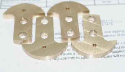
After lunch I tackled the crankwebs, now that I had all 4 discs cut out. Drilled the holes and pressed in the drill rod. I am using 1/4" for both shaft and pin:
My little arbor press was handy here. Milled the first side:
I used a 3/8" ball-end mill to get the rounded inner corner. Then the other side:
All ready to be slit:
I'm not sure whether to drill and tap the lock screw before slitting.
My first task this morning was to cut the ~6"x3" bottom plate blank out of a 9x4 piece of 1/4" brass. I could have done this on the bandsaw, but decided to mill it out with a 1/8" endmill. It took longer, but in the end I wasted less material. From the cutoff, I then cut out a piece big enough to turn the disc for the 4th crankweb. My boo-boo was to crank it a little too hard and broke the endmill. Luckily it's a double ended mill, so I still have one to go.
I was going to post in detail about another fubar I did, but I'll just summarize it by stating that when tapping a hole, look to see that you do indeed have the correct size tap in the tap wrench. :hammer:
After lunch I tackled the crankwebs, now that I had all 4 discs cut out. Drilled the holes and pressed in the drill rod. I am using 1/4" for both shaft and pin:
My little arbor press was handy here. Milled the first side:
I used a 3/8" ball-end mill to get the rounded inner corner. Then the other side:
All ready to be slit:
I'm not sure whether to drill and tap the lock screw before slitting.
I drilled right through for the tapping drill, then slit, then clearance-drilled (the bolt heads on mine are above the surface, Bogs counterbored his) with an old broken slitting blade in the slot to stop the clearance drill from going too far. That worked ok except for the time the old blade was in the wrong spot and the drill pulled straight through. If I had better drill downfeed control (must make a stop one of these days), I'd probably clearance drill & tap before slitting. You can go a little over on the clearance drill without too much trouble, but leave plenty of area for threads.kvom said:I'm not sure whether to drill and tap the lock screw before slitting.
The adjusting screw (a bit of threaded rod) is mentioned in the drawings, and later in the text where it says in passing that it will be silver-soldered to the fork end. I'd make it a tad longer than the specs call for-- one of mine only has a few threads engaged-- you also may want to go easy on the silver solder or re-thread the filleted part if you need those threads.
Great looking crank webs KV. I think that I would opt out for drilling and tapping them before you slit them. It would provide a a more stable piece for that step and it wouldn't hurt a thing. Keep up the good work. :bow:
BC1
BC1
- Joined
- Jun 4, 2008
- Messages
- 3,285
- Reaction score
- 630
Yesterday evening I had squared up the base plate and flycut the top surface. As it was still in the vise this evening I continued to drill the holes in the plate. After center drilling all of them, I came to the conclusion that the scaled metric screw for the bearing blocks was between a 6-32 and an 8-32 SAE. Since these are not visible, I decided to go with the larger screw. I used a #20 drill bit for the 8 inner holes, leaving ~.003" clearance. Since my parallels were under the points for the perimeter holes I decided to defer drilling these. I'm not sure how I will be mounting the finished engine.
I then proceeded to slit yesterdays crank webs using the borrowed slitting saw/arbor. This went nicely and quick fast. I used the same drill rods in the holes to clamp the webs parallel to the top of the vise jaws. The mill was running in back gear at 200 rpm with a feed rate < 1ft/min. The exposed radius of the saw was "just" enough to reach the small end hole.
Having been out and about in the sun all day I decided I was sufficiently tired to call it an evening, before I did something silly.
- Joined
- Jun 4, 2008
- Messages
- 3,285
- Reaction score
- 630
I spent a few hours today starting on the engine block. It took some time to square it all up as the material doesn't like big cuts or fast feeds. Too fast and it throws off dark chips and smoke. In addition it creates a lot of tough burrs, so lots of filing to debur the edges after milling each side was necessary.
The dimensions ended up right on for thickness, and about .100" large on height and width. Based on the material I have, the steam chests may be somewhat thinner than spec, so I am planning not to adjust the block width until I can measure them.
In any case, the cylinder bores are positioned relative to the center lines, so I proceeded to drill these. I am going to leave the bore at .500, which although somewhat less than scaled, is the size of my largest reamer. Were I to bore it to .590, the displacement would be 3.375 times greater than the original. As it is, the displacement will be 1.907 times.
I was concerned that scaling up the steam holes from 1.6 mm might not work, as I would presumably want the area of the opening to be approx. twice as large. Since a hole with twice the area is .089" in diameter and a hole 1.5 times 1.6mm is .094", it seems irrelevant.
- Joined
- Jun 4, 2008
- Messages
- 3,285
- Reaction score
- 630
After milling the main block, I was determined to make the rest of that bar serve for the steam chests and bearing blocks, as I have no other thick brass.
The piece destined for the steam chests was just wide enough for two, but I was afraid that if cut on the bandsaw one piece would be too small. So I used the slitting saw to slide it in two on the mill. I can say that the level of "chatter" was more like a scream, but feeding at less than 1 ft/min at 300 rpm finally got the job done. After squaring the two resulting bars, I found that the height would be less than scale, but still enough for the computed valve bore with a decent amount to spare. I then milled one side to the proper width, but left the depths unchanged. Given that the datum lines are center lines, I can drill all the holes and clean up the depths at the end (I might possibly need to reduce the depth of the block slightly as well).
The remainder of the material was 1x1", meaning that the depth of the bearing blocks will be slightly smaller than scale. Before I mill the width I need to calculate an allowance for the smaller than scale crankwebs.
So not a lot to show in finished parts, but a lot of time spent on the mill.
The scale for the valve bore is between 5/16 and 3/8, so I will need to order some drill rod. Luckily Enco is running a free shipping + 10% discount the next two days. ;D
- Joined
- Jun 4, 2008
- Messages
- 3,285
- Reaction score
- 630
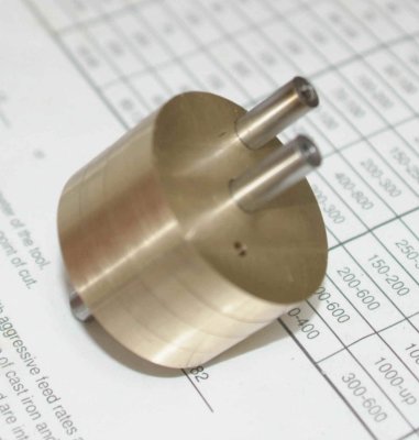
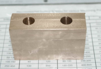
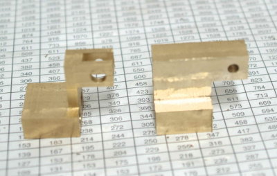
Not having any bar stock large enough for milling the crossheads, I did some calculations and found that I could get a block cut from some 2" round stock. I still has a chunk of mystery brass alloy that Cedge gave me, so I cut off a 1" slice on the bandsaw and milled it into an ablong block. This was yesterday; today I decided to continue. I didn't get far. :big: As I was drilling one of the holes for the guides, I noticed a hot spot on the side of the block. Seems this metal gets hot when drilled, and actually melted at the bottom of the hole:
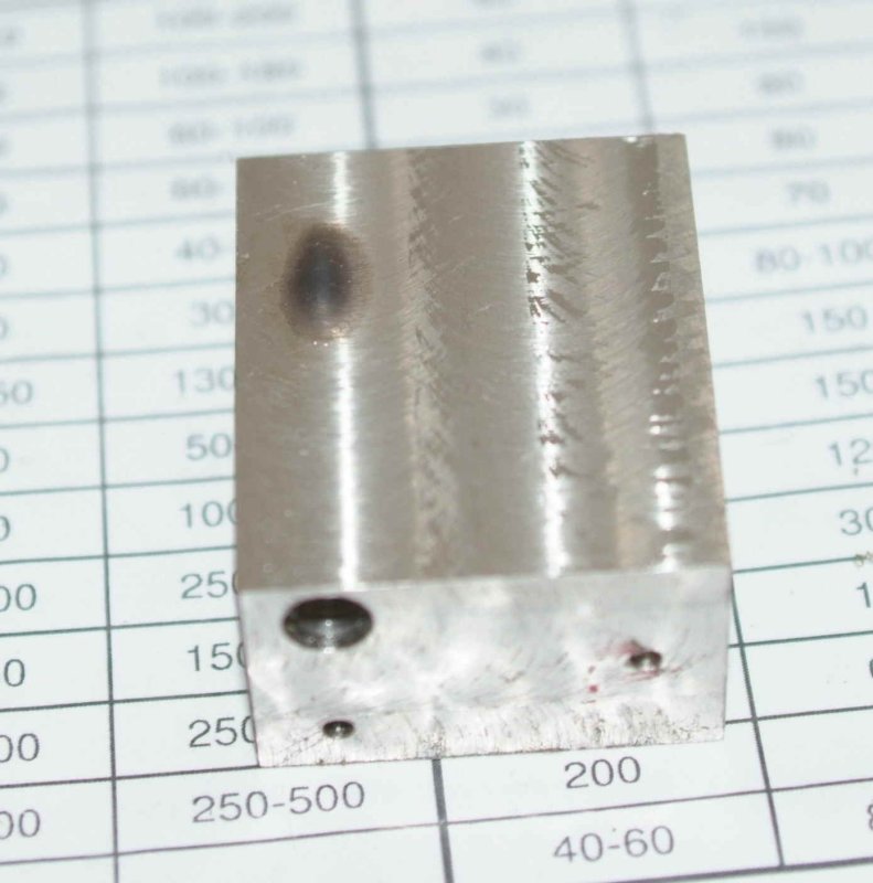
Since I also had a piece of 360 brass 2" rod, I went to Plan B and repeated the milling operation. Once I had the first block, I calculated that it was 62% of the original disc:
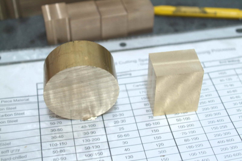
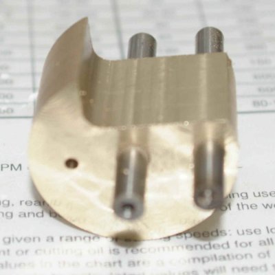
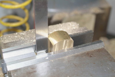
Here's the machining sequence for anyone that's interested. First, since the sides of the disc are reasonably straight, I chuck the disc in the vise with one side flat against the fixed jaw and mill one face flat to remove saw marks. Next I reverse the disc with the flat face on parallels and mill the other face. Now I can clamp the two flat faces on the vise jaws and mill one side (after calculating how much to cut). This flat side is then clamped flat on parallels to mill the opposite face. I now have something that looks like this:
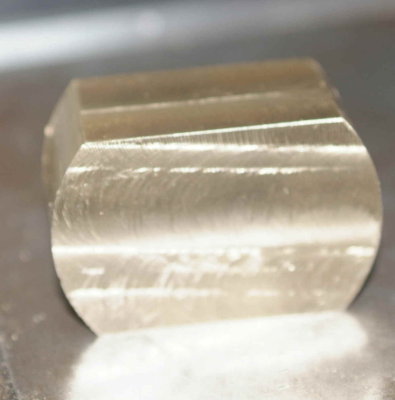
I then use a square to clamp it vertically.
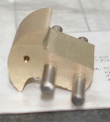
Once I had an oblong block it was a matter of carefully drilling and milling the crosshead out of it. I didn't find the optimum milling sequence, but all was fine in the end.
Hopefully I'll finish the other one the next time in the shop.
Since I also had a piece of 360 brass 2" rod, I went to Plan B and repeated the milling operation. Once I had the first block, I calculated that it was 62% of the original disc:
Here's the machining sequence for anyone that's interested. First, since the sides of the disc are reasonably straight, I chuck the disc in the vise with one side flat against the fixed jaw and mill one face flat to remove saw marks. Next I reverse the disc with the flat face on parallels and mill the other face. Now I can clamp the two flat faces on the vise jaws and mill one side (after calculating how much to cut). This flat side is then clamped flat on parallels to mill the opposite face. I now have something that looks like this:
I then use a square to clamp it vertically.
Once I had an oblong block it was a matter of carefully drilling and milling the crosshead out of it. I didn't find the optimum milling sequence, but all was fine in the end.
Hopefully I'll finish the other one the next time in the shop.
- Joined
- Jun 4, 2008
- Messages
- 3,285
- Reaction score
- 630
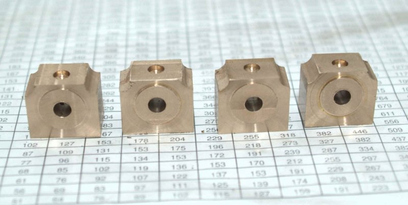
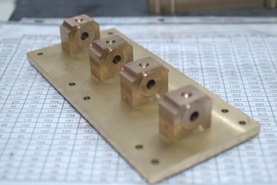
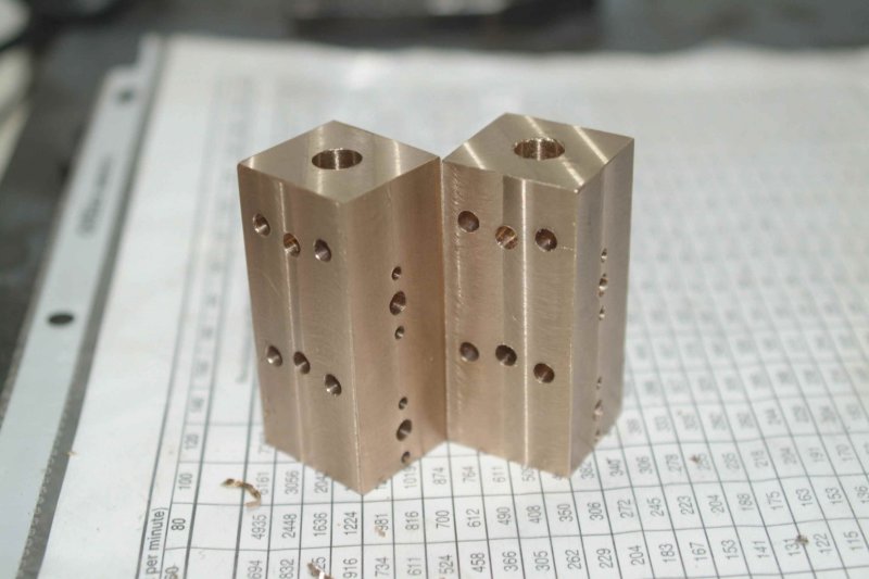
Rather than finish the other crosshead, I decided to work on the bearing blocks that I had roughed out last week. It was tedious work, but nothing fancy. The vise stop saves a lot of time in repetitive operations on multiple parts. I did drill the oil holes before reaming the bores so as to avoid burrs.
For turning the bosses on each side, I used the same fixture I used for the eccentrics: a piece of aluminum round drilled and tapped 1/4-20. The first one turned out poorly, with a lot of tearing. I was using a medium speed and slow machine feed on the crossfeed. This alloy needed just the opposite: lots of RPMs and fast feed. Here's the results:
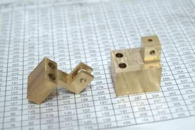
I did discover a potential problem. I drilled the holes for mounting the blocks on the base plate according to the plan. However, the material I had for the blocks was smaller than spec, so the blocks ended up .18" shorter in the longest dimension. Fortunately the blocks cover the holes, but using the planned 8-32 screws to attach them will mean that the tapped holes in the base of the block will be extremely close to the edges. I think I will just use 5-40 screws, leaving more "meat" around the holes. However, I'm going to sleep on it before making any decision. I could conceivably drill a second set of holes in the plate inside the ones I already drilled. In any case, I have not drilled mounting holes in the base of the blocks.
Any other ideas are welcome.
For turning the bosses on each side, I used the same fixture I used for the eccentrics: a piece of aluminum round drilled and tapped 1/4-20. The first one turned out poorly, with a lot of tearing. I was using a medium speed and slow machine feed on the crossfeed. This alloy needed just the opposite: lots of RPMs and fast feed. Here's the results:
I did discover a potential problem. I drilled the holes for mounting the blocks on the base plate according to the plan. However, the material I had for the blocks was smaller than spec, so the blocks ended up .18" shorter in the longest dimension. Fortunately the blocks cover the holes, but using the planned 8-32 screws to attach them will mean that the tapped holes in the base of the block will be extremely close to the edges. I think I will just use 5-40 screws, leaving more "meat" around the holes. However, I'm going to sleep on it before making any decision. I could conceivably drill a second set of holes in the plate inside the ones I already drilled. In any case, I have not drilled mounting holes in the base of the blocks.
Any other ideas are welcome.
Maryak
Well-Known Member
- Joined
- Sep 12, 2008
- Messages
- 4,990
- Reaction score
- 77
kvom said:I think I will just use 5-40 screws, leaving more "meat" around the holes. However, I'm going to sleep on it before making any decision.
Kvom,
Reads like that's the best option.
Best Regards
Bob
- Joined
- Jun 4, 2008
- Messages
- 3,285
- Reaction score
- 630
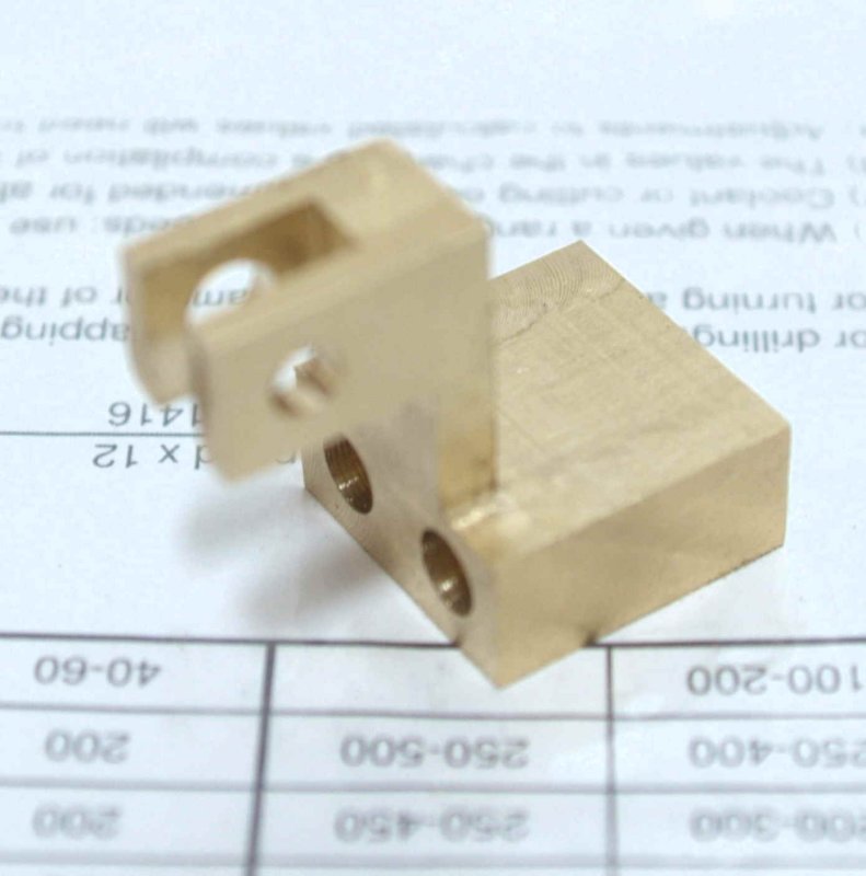
My first goal of the afternoon was to finish milling the second crosshead. I did it in a different sequence, and although it required an extra reclamp in the vise, I was able to clamp solidly against the jaws more often. The first operation was to expose the conrod bracket (three cuts in one vise position):
Then two cuts on the "cheeks":
Afterwards it was just the cross cut on the Y-axis and milling the slot.
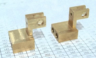
After patting myself on the back and enjoying a soft drink, I drilled and tapped the bearing blocks.
There was just enough room for the 5-40 screws. Right now the bores are a tight fit on some 1/4" drill rod that I lapped with some fine sandpaper. I need to do the same thing with a longer piece to lap out the bores and align the blocks precisely on the plate, as shown in John's writeup. I'd like to get the base cutouts done next so that I can trial fit the eccentrics and cranks.
Then two cuts on the "cheeks":
Afterwards it was just the cross cut on the Y-axis and milling the slot.
After patting myself on the back and enjoying a soft drink, I drilled and tapped the bearing blocks.
There was just enough room for the 5-40 screws. Right now the bores are a tight fit on some 1/4" drill rod that I lapped with some fine sandpaper. I need to do the same thing with a longer piece to lap out the bores and align the blocks precisely on the plate, as shown in John's writeup. I'd like to get the base cutouts done next so that I can trial fit the eccentrics and cranks.
- Joined
- Jun 4, 2008
- Messages
- 3,285
- Reaction score
- 630
Thanks for all the advice. I'm actually looking foward to trying it. I'll use the citric acid as it sounds simpler and safer.
Today I had a couple of hours in the shop before going off to school. Ny task today was the cutouts on the base plate. I started by measuring the faces of each of the bearing blocks with an edge finder. I then used my height gauge scribe to make very faint marks on the plate. These were just as checks on where the cutout corners are supposed to go. Since I was going to use a 1/4" endmill, I spot drilled each corner 1/8" in from the computed dimensions, using the scribed lines as a check. I then drilled 1/4" holes (end mill is the type with the small hole in the center, hence not useable as a dril).
Here's the result:
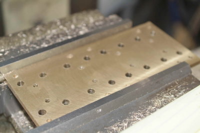
Next I made all the horizontal cuts using the table feed:
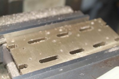
The Y-axis slots I had to do by hand.

After deburring the edges I remounted the bearings to check my work. I looks as if I will need to slightly enlarge under one of the bearings a bit.
I had a little time left, so I drilled and tapped the lock screws for the crank webs (did I ever mention I hate tapping?)
Today I had a couple of hours in the shop before going off to school. Ny task today was the cutouts on the base plate. I started by measuring the faces of each of the bearing blocks with an edge finder. I then used my height gauge scribe to make very faint marks on the plate. These were just as checks on where the cutout corners are supposed to go. Since I was going to use a 1/4" endmill, I spot drilled each corner 1/8" in from the computed dimensions, using the scribed lines as a check. I then drilled 1/4" holes (end mill is the type with the small hole in the center, hence not useable as a dril).
Here's the result:
Next I made all the horizontal cuts using the table feed:
The Y-axis slots I had to do by hand.
After deburring the edges I remounted the bearings to check my work. I looks as if I will need to slightly enlarge under one of the bearings a bit.
I had a little time left, so I drilled and tapped the lock screws for the crank webs (did I ever mention I hate tapping?)
") you'll get lots of tapping practice, like it or not.. I think there are 50+ screws and attendant tapped holes on this thing.
you'll get lots of tapping practice, like it or not.. I think there are 50+ screws and attendant tapped holes on this thing.Clearance around the bottom of the bearing blocks is also a good thing-- if the crank rods stick out even a little, they have a habit of banging into any protruding baseplate bits.
- Joined
- Jun 4, 2008
- Messages
- 3,285
- Reaction score
- 630
I had a few hours today interupted by several honey-dos. Got the steam check holes drilled. I am going to hold off on reaming the valve bore until I'm ready to fit the valves. I decided to go with a .375" bore and ordered some drill rod of that size today. In any case I drilled the bore 1/32 smaller. The steam ports are .177". The flange mounting screws will be 5-40. I didn't tap these yet (did I mention I dislike tapping?). For mounting the steam chest to the block I will use 8-32 screws, hence the mounting holes are drilled accordingly.
I also made a flywheel from the Cedge mystery alloy (silver bronze). It's hard to work with, but is very "pretty" when polished. I used the badsaw to cut off a 5/8" slice from the 2" diameter rod, but since the saw didn't cut straight the wheel ended up .55" thick rather than the scale .59". I wanted to machine a rim/hub recess, and normally would use a parting tool. However because the cross slide on my lathe has a very short travel, the parting tool in the QCTP holder won't go close enough to the center. So I needed to grind a HSS tool blank into an appropriate cutter. That took quite a while, but gave me a chance to use the new 46-grit grinding wheel for the first time. I plan to bling it up a bit, but here's the first version mounted up for a trial fit:
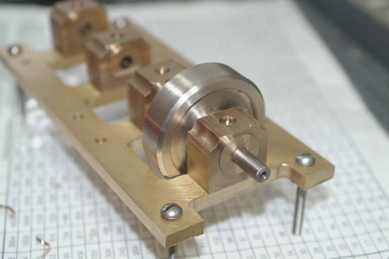
I also made a flywheel from the Cedge mystery alloy (silver bronze). It's hard to work with, but is very "pretty" when polished. I used the badsaw to cut off a 5/8" slice from the 2" diameter rod, but since the saw didn't cut straight the wheel ended up .55" thick rather than the scale .59". I wanted to machine a rim/hub recess, and normally would use a parting tool. However because the cross slide on my lathe has a very short travel, the parting tool in the QCTP holder won't go close enough to the center. So I needed to grind a HSS tool blank into an appropriate cutter. That took quite a while, but gave me a chance to use the new 46-grit grinding wheel for the first time. I plan to bling it up a bit, but here's the first version mounted up for a trial fit:
- Joined
- Jun 4, 2008
- Messages
- 3,285
- Reaction score
- 630
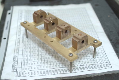
Today I decided to make the upper plate, as I had limited shop time available. I started with a 4"x4" piece of .25" thick brass plate that had been flycut on one face. After squaring the sides I used a 1/8" endmill to saw the short side, then used an endmill to bring to the final dimensions.
Since all of the holes are or can be referenced from the center, drilling them was an exercise in cranking the handles and watching the DRO. I drilled all of the mounting holes to take 6-32 screws. The large holes for the glands needed to be slightly over 1" in diameter. I used a 3/4" end mill (my largest) to make the initial hole, and then the boring head enlarged them to ~1.05 (loose fit around the gland).
I didn't make any cutouts as I want to see how the plate looks when mounted before deciding on any blingification.
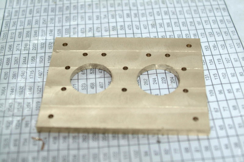
As I was taking the photo UPS arrived with my 3/8" drill rod, so machining the valves may be the next task.
Since all of the holes are or can be referenced from the center, drilling them was an exercise in cranking the handles and watching the DRO. I drilled all of the mounting holes to take 6-32 screws. The large holes for the glands needed to be slightly over 1" in diameter. I used a 3/4" end mill (my largest) to make the initial hole, and then the boring head enlarged them to ~1.05 (loose fit around the gland).
I didn't make any cutouts as I want to see how the plate looks when mounted before deciding on any blingification.
As I was taking the photo UPS arrived with my 3/8" drill rod, so machining the valves may be the next task.
- Joined
- Jun 4, 2008
- Messages
- 3,285
- Reaction score
- 630
A full afternoon's work in the shop resulted in exactly one useable part:
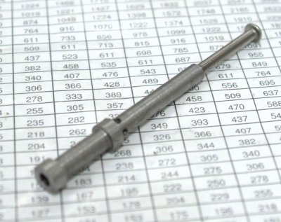
The two other valves that I started ended up in the scrap bin because of various operator errors. On the positive side I did learn the best way to turn this rod to get a better finish, and I can probably make a valve in less than half an hour if I don't mess up.
I decided that the lathe karma was lacking, and decided to move to the mill for a "simple" piece, the blanking plates. Well I messed up there somehow as the holes didn't end up centered. So I figured it was time to call it a day.
As for wiggle room, I think I need to plan for that on the steam chest/blanking plates. I drilled the holes with a #20, which is a close fit for an 8-32 screw. Using the DRO to drill the holes for the plate, I found that the screws would "just" go through the plate and the steam chest. I plan to enlarge these holes by a couple of thousands so that when attached to the block I will be able to wiggle them slightly in case the bores on the block and steam chest are not perfectly aligned.
kvom,
Don't you love it when you learn something new every day...today you made one part, tomorrow one more part and before you know it you'll have a sweet little engine.
By the end of it and when you start the next one there will be more challenges but less mistakes, better parts = nice engines.
Keep it up :bow: the good work...by the way :bow:
Regards
Philly
Similar threads
- Replies
- 44
- Views
- 8K