Maryak
Well-Known Member
- Joined
- Sep 12, 2008
- Messages
- 4,990
- Reaction score
- 77
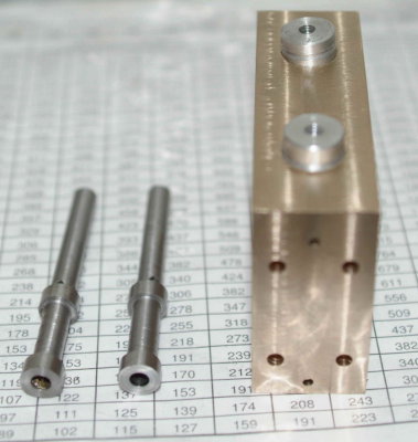
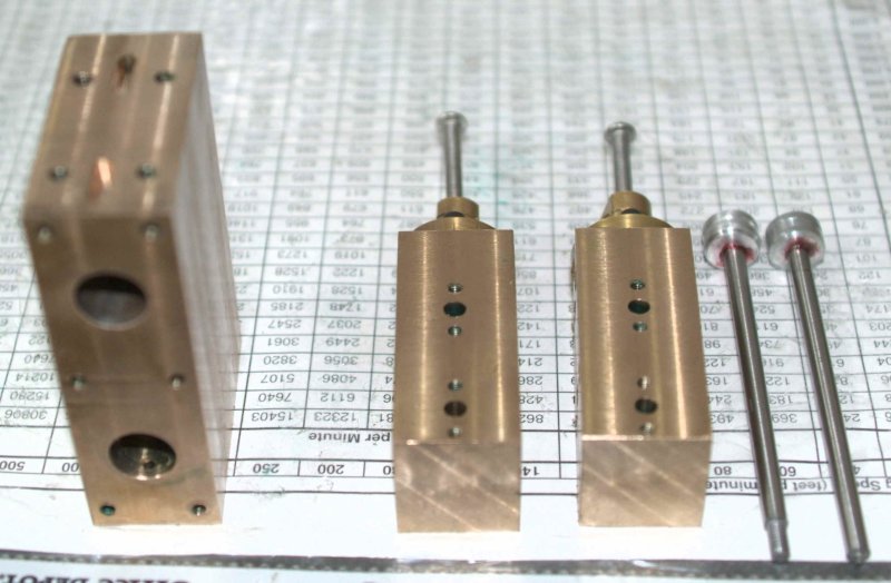
kvom said:A full afternoon's work in the shop resulted in exactly one useable part:
I can probably make a valve in less than half an hour if I don't mess up.
See you gained quite a bit but sometimes it sure doesn't feel like it.

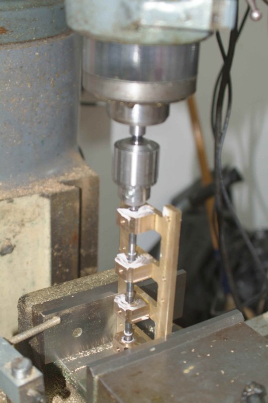
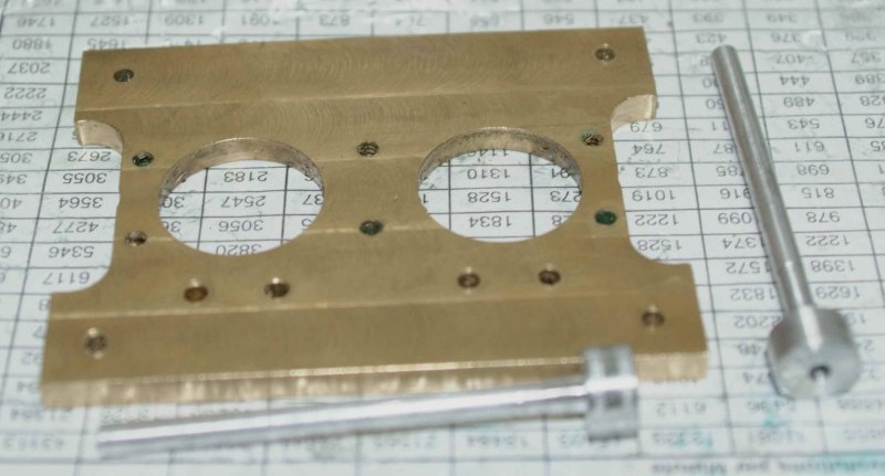
kvom said:I decided that the lathe karma was lacking, and decided to move to the mill for a "simple" piece, the blanking plates. Well I messed up there somehow as the holes didn't end up centered. So I figured it was time to call it a day.
An excellent decision, trust you imbibed some suitable fluids to maintain your electrolyte balance.
Best Regards
Bob