Another Paddleducks Build

Home Model Engine Machinist Forum

Help Support Home Model Engine Machinist Forum:

This site may earn a commission from merchant affiliate links, including eBay, Amazon, and others.
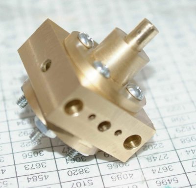
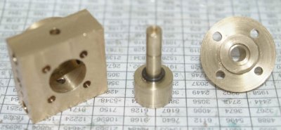
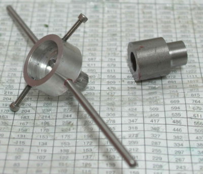
Today I started on the steam control block, which is the last component needing to be machined and the last assembly that can be completed until I am able to silver solder pieces together. Here's the block and spool, along with the elements of the eccentric linkage completed since the last photo:

large.jpg


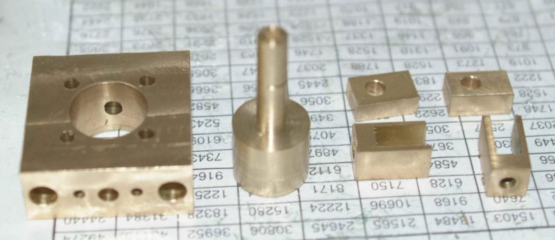
I made several errors in machining the block, none of which I think (hope) will require remaking it.

The first issue was in drilling the mounting holes for the flanges. I was using the vise stop to center all of the holes on the edges, and apparently a piece of swarf or something got between the block and the vise jaw, causing these holes to be slightly off center. To work around this, I will need to offset the mounting holes in the two flanges, but this seems reasonably easy to do.

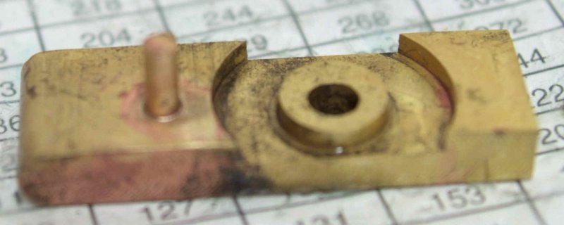
The second issue was in the size of the 4 steam holes. I just scaled these up from the 4mm plan spec, which means I drilled them 15/64. I should have realized that I would be soldering 1/4" tube into these holes. Since I machined the block out of 2" round stock, the block is slightly smaller than the plan scale would require (1.4" each side vs. 1.47"). This means that the holes are closer to the edge, and enlarging them would make them even closer. However, it appears that I can enlarge the holes to 1/4" while keeping enough material between the hole and the edge.

Finally, I made the center hole overlarge. I entended to drill it to 1/2" and then bore to .59". To save time I drilled the hole using a 1/2" endmill. At least the shank was 1/2" but the flutes made it a 5/8" endmill. So after boring, the hole ended up with a diameter of .645". This can seemingly be handled by making the spool larger to fit, and that's what I did. I also made the spool shaft slightly oversize at 1/4" as I need to find an o-ring with a matching ID. Once I get the O-ring the front and back caps can be machined.
 
I had a full afternoon in the shop making the front and back plates for the steam control. It took a lot longer than I expected as I had to turn both pieces down from 2" brass round, and I wanted to keep the waste of material to a minimum. In addition, the boss on both is a close fit to the block, so some attention and repeated measurements took time. I had located a 1/4" ID by 3/8" byt 1/16" O-ring at the local hardware store this morning, so I had what I needed.

Here's the assembly:

medium.jpg


I didn't have any 6-32 SHCS so had to use these for the trial fitting. I had been thinking of using stud and nuts here, but standard 6-32 nuts are too large and inerfere with the shaft.

The rear cap turned out to be a press fit to the block, so after screwing it in tio align the holes I pressed it in with the arbor press. I don't see it coming out again. I realized at that point that this part is unnecessary if you have the ability to bore a blind hole in the block for the spool.

Once I could measure the depth of the hole and the size of the boss on the front cap I could mill the spool to length. I probably cut it too close as once the 4 pieces are fastened tightly together there's a lot of friction; I can turn the spool holding it with pliers, but not with finger pressure alone. I imagine there is friction between the end of the spool and the bottom cap as well as the sides and the o-ring pressing against the front cap. Once I make a handle I'll be able to assess if it's too tight.

Here's the parts disassembled. I still need to mill the slots, pending some thoughts on other dimensions.

medium.jpg


On the soldering front I located local sources for both firebrick and citric acid, so tomorrow I should have everything needed to get started. The first joints to be attempted will likely be the eccentric straps to the linkage blocks.
 
Cool.. I've been sidelined making the spool and control block ends for a while now. That's looking nice.

 
very nice, and surely efficient, steam control
well done kvom!!!

 
kvom,

Very nice :bow:

Best Regards
Bob
 
I finally got back in the shop this afternoon. The first order of business was to finish up and test something that a lot of people here have made: a diestock for the lathe:

medium.jpg


The small part is 1" CRS drilled and reamed .5" and turned down to .65", which is the largest diameter the lathe chuck can clamp.

The larger part started as 1-3/8" aluminum round, bored 1" x .4" deep for the die, with the opposite end turned to .5" to fit the other part. Handles are 3/16" drillrod, and screws are 6-32 (I'll cut them down some later).

I also made a second try at silver soldering, and this time it seemed to go a lot better. Here's the joint in a piece of scrap after 1 hour or so in the pickle:

large.jpg


This time I used a very little flux and chamfered the hole manually with a countersink.
 
it's perfect kvom, but...

all my tests go always well, perfect like your piece
then, when it's time to solder seriously, lot of problems from everything :big:

 
Past few days in the shop have been dedicated to working on the Jeep, after breaking a control arm bolt on Saturday that also resulted in a busted shock absorber. :mad:

That said, this morning I took a little while off wrenching to silver solder the eccentric straps. This is the result after 2 hours of pickle soak:

medium.jpg


I used 3/16" drill rod turned down to .150" on each end.
 
Crawling under the Jeep replacing shocks left not much time for any engine building, esp. as I have a sore back as a reult. That said, I spent a couple of hours making some temporary air inlets, copied from shred:

large.jpg


I also had to re-do soldering one of the eccentric straps. Seems as if the solder did not go where it was supposed to.

Seems as if the only machining needed to be able to try out the engine under air is to fabricate the pins for the eccentric joint and thread the piston rods for connecting to the crosshead, and then I can try to put it together and do the "tuning". If I can get it to run then I'll need to make some feet and try to figure out if I'm going to make the bent copper lines like shred or make the straight flanges. I'd like to make gbritnell's tube bender, so I will investigate that option soon.
 
Good plan making them to use flexible hose. I thought I'd be all clever and soft-solder mine to the copper pipe in-situ and ended up soft-soldering one of the inlets to the block. ::)
 
With all the working pieces fabricated, I wanted to put it all together for a trial fit. Here's the result:

large.jpg


It's not quite ready to run yet, as it's still too stiff to turn by hand. The main culprit is the right hand piston rod, which binds in the gland. I think I will progressively test each eccentric and each piston separately to try to get them loose enough so that the tuning process can be done. The bottom end (crankshaft) does turn by hand fairly easily, and the valves and one piston slide freely when not connected, so hopefully I can get it to run quite soon.
 
you have almost finished kvom, compliments, very nice engine :bow: :bow: :bow:

surely you'll achieve your goal and the engine is going to run soon

we are waiting for see it
 
Looks great.
Really appreciate your comments on getting the engine ready to run.
I'm learning a lot here.
 
Aside from making a rough set of support bars from 1/2" square brass bar to replace the 4 screw "feet", I've been spending what shop time I have in doing the fiddly bits to get it ready to run.

With some advice from others I went back to square 1 to ensure that the crank assembly is straight. After verying the bearing blocks on the durface table, I re-deburred the mounting holes and opeining in the base plate. Upon reassembly I can now turn the entire crank and components with finger pressure. Previously I was getting some binding. There are lots of parts that slide together on this engine, so getting all the sticky parts to work together can be tedious.

I will ensure that the crank is parallel to the centerline by mounting the base in the mill vise and using an edge finder at each end.

My summer CNC class starts up again tonight, and I hope to use the Haas to turn 4 "bling" columns. I would also like to make some dies to use in making gbritnell's tubing bender.
 
My first try at running failed. ???

I went through the chapter on tuning, and as far as I can tell the various components are set as indicated. I tried to adjust the bottom with the engine assembled, but found that tightening the crank webs sufficiently was a problem. Having a set of T-handle allen wrenches would have been an advantage. So I removed the top to adjust the bottom. Of course, when I put it back together things were stickly again. Eventually, as usual, the issue is traced to the crosshead guide rods, which seem to have to be "just so". I decided to ignore the problem for the time being and removed one of the rods from each crosshead.

My bits of threaded rod connecting the valves to the eccentrics were too long, so I had to reduce the lengths to get the valves set in the indicated positions. Once that was done I screwed on the top caps and replaced the blanking plates.

Then I discovered that while the input barb for the engine is for 1/8" tubing, my regulator takes 1/4". Sp it was off to the local hardware looking for a reducer with different size barbs on each end. No luck there, so I came home intending to make one on the lathe. While rummaging in some storage drawers, I found a Schrader valve with 1/4" NP threads, so I decided to put that as the engine input and hook up the regulator used for filling tires. ::)

Since it takes two hands to maneuver the hose, I couldn't see everywhere the air was escaping (engine didn't turn whatsoever). I did see oil all over one of the joints between the block and the steam chest. I need to enlarge the holes in the blanking plates and shorten a couple of the screws to get a tighter seal. I'll also make a double barb connector so that I can run the air hands-free and try to see where the leaks are.

Any other ideas gratefully solicited.
 
A little leaking isn't fatal by any means. With a decent compressor pushing a good volume of air in at 50+ PSI, leaks won't matter (make sure air is getting to the right places at least-- a leak could be the only exit if a passage is blocked, but other than that, leaks can be dealt with later). I still haven't put sealer in mine and it leaks quite a bit as well as having imperfect valve timing.

I needed a good strong hex key and a degreasing of the crankshaft rods to make it all stay put. The crank takes a lot less force when the engine is actually running, so don't sweat it if it moves a little when you lean on it hard by hand (it's just annoying and frustrating, is all ;))

Binding and tight spots are what you need to chase down and get rid of.

I blamed the crossheads for a lot of things that were really glands and packnuts binding and slightly off-round valve spools (those are tricky-- with the engine apart everything looks and feels good.. assemble and rotate a little timing it in and now they're dragging..)

Getting the timing 180 degrees out manifests itself as the engine kicking over a little when you turn it over by hand with air applied, but not all the way. Proper eccentric timing is the fat part of the crank webs at the same side of the engine when their respective eccentric is all the way lifted up (obviously the two cranks are still 90 degrees apart, so they aren't both on the same side at the exact same time, it's the relationship of crankweb-to-eccentric that's key).

Keep at it as time allows-- tune one part at a time, don't be afraid to take stuff apart and work on the subassemblies one at a time and you'll get there. It took me quite a while to get mine to run the first time as well. Oh yeah, if you're using the temporary intakes, try switching them to the other set of ports every so often-- sometimes it really prefers to run one direction than the other.

Here's a copy of the MM post for completeness here:

Shred said:
Since I just went through and re-turned my engine the other night, here's how I went about it-- Starting with an assembled engine that doesn't want to run, even if timed correctly (check this! I messed it up for days of frustration)

1 - Separate the top and bottom halves. Pull the piston and valve pins and undo the tops of the columns. Now you have the crank half separate from the block half .
2 - While you are separating, check the con-rods and eccentric joints are free-- I found that bead-blasting peened one enough to rub. Fix those.
3 - Make sure the crank and bits turn free (dangle it upside down or whatever to keep the con rods and eccentrics from crashing into things). The crank must be smooth and free-running through 360 degrees, no binding, or rough spots. Often a little bit of bar protrudes or a crank web or con-rod rubs on something else. Fix all of that, then set the cranks and timing on the bottom end and set it aside.

4 - Now address the top. Without mucking with it (you took it off an engine you thought would run, right?), pull and push the various rods. Run them to the full extent of their travels-- take note of any drag, friction, binding and rough spots. Drag going from one direction to the other at the ends of the travels is a bigger problem than a little running friction between the end points and often indicates an alignment issue.
5 - Starting one at a time, with one moving part (one valve or one piston), fiddle with the adjustments. Bogs left a ton of adjustments in this thing. So many sometimes it's hard to know what to fiddle with. Loosen everything up-- gland bolts, packnut (undo it completely), crossheads, etc and make sure the main bit moves correctly and smoothly. If not, fix it. Then start tightening stuff back up, starting with the gland bolts, then the packnuts, then the crossheads checking all along the way, both ends of travel, fixing the problems that come up.

6 - If there are alignment problems, you may have to drill some holes a little larger to get more wiggle room. If something is way out of wack, you'll probably need to redo it. One adjustment to play with as well is the main block baseplate. That has wiggle room and alignment for the crossheads as well. Pull the glands and pistons all the way out, then put them partway back onto the crossheads, so the piston is just out of the cylinder-- do the pistons line up with the bore? If not, tweak the baseplate over a bit so they do.

7 - Fiddle with the crossheads and get the pistons running as smoothly as possible.

8 - Recheck and reassemble. Time the valve spools and apply air. If your valve spools only run free in one orientation, you'll have to be careful when setting the timing-- set it by screwing the joint, not by rotating the spool.

Hope this helps
- Roy

...and in a later post...

A couple other things I forgot to mention earlier was when tuning the assembled engine:

--- I chucked the end of the crankshaft in a small drill chuck (use a tailstock chuck if you haven't got a loose drill chuck running around. I have no idea how I got so many loose chucks.. they must breed under the bench). That is much easier to turn by hand and get a good feel for what's going on than trying to push the flywheel around. Don't try and run the engine with a chuck hanging off the end.

-- Another thing to try when tuning is loosening the middlemost crank web on the #1 (awaymost from the flywheel) piston, disconnecting the front end of the engine from the other. If needed, you can make an extendo-rod for the front end eccentric and turn just the front end as well. The engine won't run like that without a much larger flywheel, but you can get a feel for where the problems are by turning over by hand and with pressure applied.
 
kvom said:
My first try at running failed.

No, no failure yet. This is first run at adjusting and tuning. So far you've only had success. Looking forward to the video of it running.
 
Shred,

Thanks for the feedback. As soon as I make the air connector and free up my hands, the first thing I want to do is remove the top caps to ensure that air is entering the cylinder. Since the crank does turn with finger pressure, I would expect that a pressurized cylinder would at least cause th pistons to move.

It will work eventually I'm sure.
 
[ame]http://www.youtube.com/watch?v=GlX9dvjIcgA[/ame]

;D

I haven't been posting my birthing pains here, but it has taken a fair number of disassemblies and fiddling to get it to run longer than a few seconds. Today was the magic hour.

Run in the video is with 1 guide rod per crosshead at 40 psi. The engine still needs to have 1 piston just past TDC to self-start, but once started it will run for minutes on end. Perhaps I need to do the 10 hr. run in that Bogs did. The only change I made since last night was adjustting the #2 valve a few degrees. It then ran for 4-5 minutes until stopping.

I then discovered that the vibrations had loosened the grub/set screws on the #1 valve allowing the timing to go off. On the second long run the same thing happened on the #2 valve screw. I am thinking that the #2 eccentric can be loctited to the shaft without causing any problems. For the #1 valve I might need a deeper notch in the shaft or else a hole drilled into the notch.

I'm guessing the reason the engine won't self-start in all positions is that there is still a fair amount of static friction to overcome, and that a half-stroke of the piston doesn't generate enough momentum. It might be interesting to mount a heavy metal disc on the end of the shaft. One area of friction that I'm aware of is between the eccentric clevis and fork. I think a bit of filing on each will help the next time I do a disassembly.

Another thing to try is moving the air to the lower inlets to see how it runs in reverse.
 
kvom,

Congratulations on a successful build. :bow: :bow: :bow:

Best Regards
Bob
 
Back
Top