Another Paddleducks Build

Home Model Engine Machinist Forum

Help Support Home Model Engine Machinist Forum:

This site may earn a commission from merchant affiliate links, including eBay, Amazon, and others.
Good work, kvom :)

It must have been frustrating, but it has to be worth it in the end, hey?!

What's next? ;D

Gordon
 
Now I need to finish the reversing spool valve, but that will require making George's tubing bender. I'm also making new columns on the CNC lathe at school; hopefully they will be done next week.

Then there will be a lot of bling polishing to do.
 
Congratulations kvom!

Looks like a really nice runner :bow:
 
Congratulations Kirk!

Beautiful build!!! Thm:

Rick
 
Sweet!

The eccentrics on mine pretty much stay put on the shaft flats with just a setscrew, but there's probably not much harm in sticking them there a little more permanently or loctiting the setscrew at least.

 
I knew you would get it! Hurray. woohoo1 woohoo1 woohoo1

Ron
 
congrats kvom, very nice running engine :bow: :bow: :bow:

perhaps it isn't many blingy at first glance, but it is a quite difficult work that requires many skills and work and patience

very well done!!!


Congratulations!! Looks great and sounds real smooth.

Nicely done.

Kevin.
 
There's still work to do on this, especially the control/reverse valve. I need to make a tube bender for this. I'm also making some nicer columns at school on the Haas CNC lathe.

Today, on advice from Bogs, I injected motor oil into the air lines as an aid in "bedding" the engine. I ran it for an hour, with many intermittent stops. Since it vibrates quite a bit, I had various fasteners loosening up. I needed to tighten up the piston gland nuts with a wrench. I also found that the screws holding one of the steam chests had gotten a bit loose allowing it to tilt slightly and pinching the valve stem.

At the end of the hour it would run a bit more smoothly and at 30 PSI. It still doesn't self-start unless one of the pistons is just past TDC. I notices at the end that the jam nuts on the valves had worked loose as well, so I think it's likely that the valve has adjusted itself further out.

I'll keep working on it. Since the compressor runs full time when the engine is working an hour at a time is about all I can stand.
 
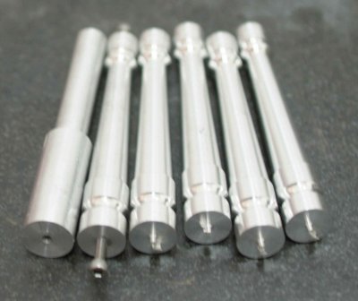
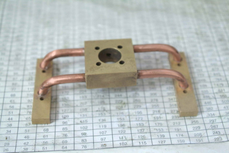
I finally was able to get the columns made on the CNC lathe at school.

medium.jpg


On the left is a temporary column, followed by one that's been tapped and the others I need to drill and tap. To get the same profile manually would have required grinding some form tools, plus cutting the taper either with the TA or the compound. This was my second project for actually making a part, and the first that I designed myself. There were two g-code programs:

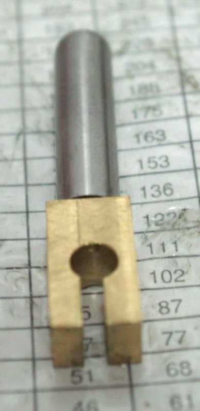
The raw material was 5.5" lengths of 1" 6061 rod. For the first program, the rods are clamped in a 1" collet with 2" exposed. This program faces the rod and turns the 1st .5" down to a diameter of .49". It then centerdrills to form a 60 degree chamfer, then drills 3/4" deep with a #36 drill for later tapping 6-32.

For the second program, the pieces are clamped with 4.5" exposed. A live center is used in the chamfer created in step 1. The program turns the profile using a 3mm round tool, then parts off the column at a length of 4.16", a few thousands overlength.

To finish for mounting, I chucked the column on the lathe using a rubberflex collet, with the bottom exposed. I could then face the bottom and drill and tap for the 6-32 mounting screw. I then tapped the top end at the workbench. Once I do all 4 I'll use the height gauge to measure each one, and then face so that all 4 are the same length to with .001.
 
kvom,

Great columns. :bow:

Best Regards
Bob
 
Getting a little more done on this. I drilled/tapped/mounted the new columns, and also made a pair of flanges for the input/exhaust pipes. I decided to make 1-piece flanges rather than separate, and I think that will make the fitting a bit easier when I finally get the little tube bender finished and can attach the valve assembly.

medium.jpg
 
Here's a photo log of progress on the engine.

First, the mini tube bender for making the 90 degree bends in 1/4" tubing:

large.jpg


A trial fit once the tubes are trimmed:

large.jpg


The side flanges with some temporary tubes for fit:

large.jpg


The top/bottom plugs soldered:

large.jpg


And them milled flush:

large.jpg


The tubes soldered into the valve body:

large.jpg


The handle for the valve:

large.jpg


Valve after soldering tubes to the flanges:

large.jpg


And the problem gaps where the tubes enter the flanges:

large.jpg
 
Could you not just add more flux, another ring of solder and resolder? Keep the heat on the flanges and you should be ok. IMHO.

Just soldered up my control block. Everything went well even though I missed the part where Bogs said to use 2 rings of solder on the joints. I used 1 ring, still got nice fillets.

Am taking pics and will post them at a later date.

A bit off topic but... Trying to get shop ready for new addition http://www.grizzly.com/products/10-x-22-Bench-Top-Metal-Lathe/G0602

Really like your tubing bender. Thm: Thm: Thm:


Ron
 
Looking good. A pickle soak and re-solder with another ring of solder should fix up those tube joints in no time.
 

Latest posts

Back
Top