Well, time to get back to the Alpha Stirling project. I have being busy playing with old gas engines and my Mustang all summer, but now the leaves are falling and the daylight is getting shorter, time to build engines ;D
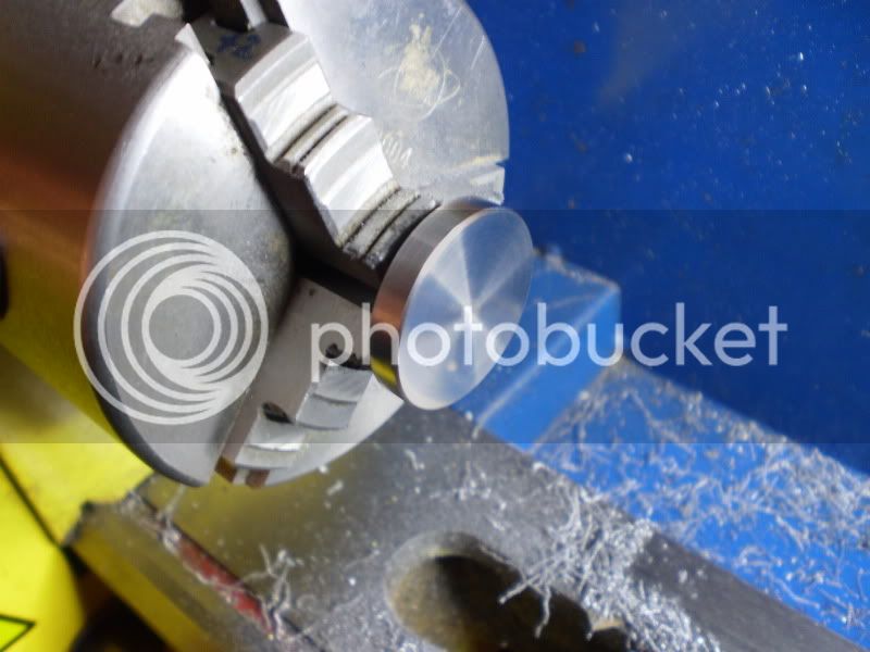
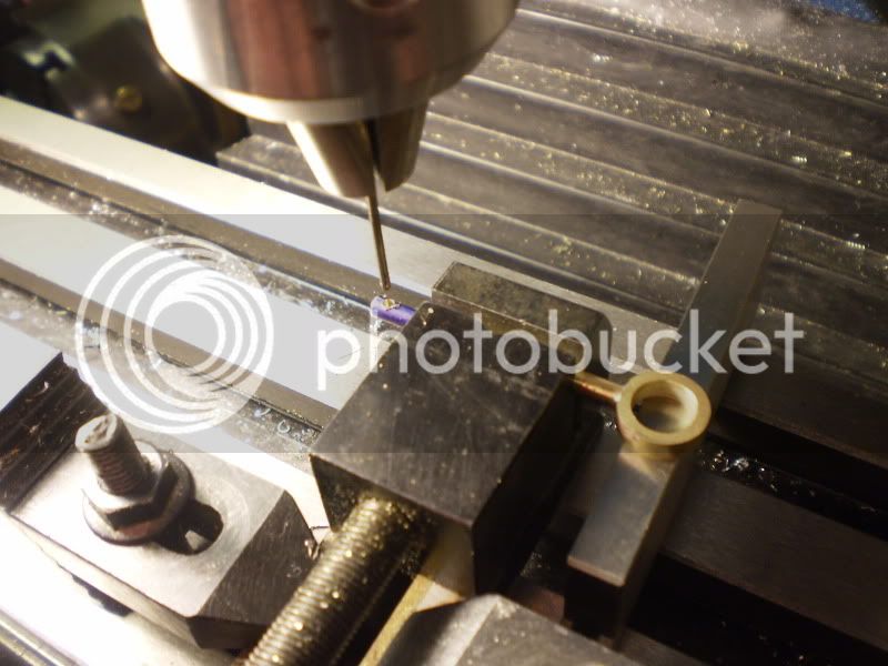
Next was to make the piston rods. These are simple creations made from 1/8" brass rod, silver soldered to a brass ring finished to 0.374" ID ( I love over/under reamers ;D) A 1/16 hole was drilled in the end for the wrist pin.
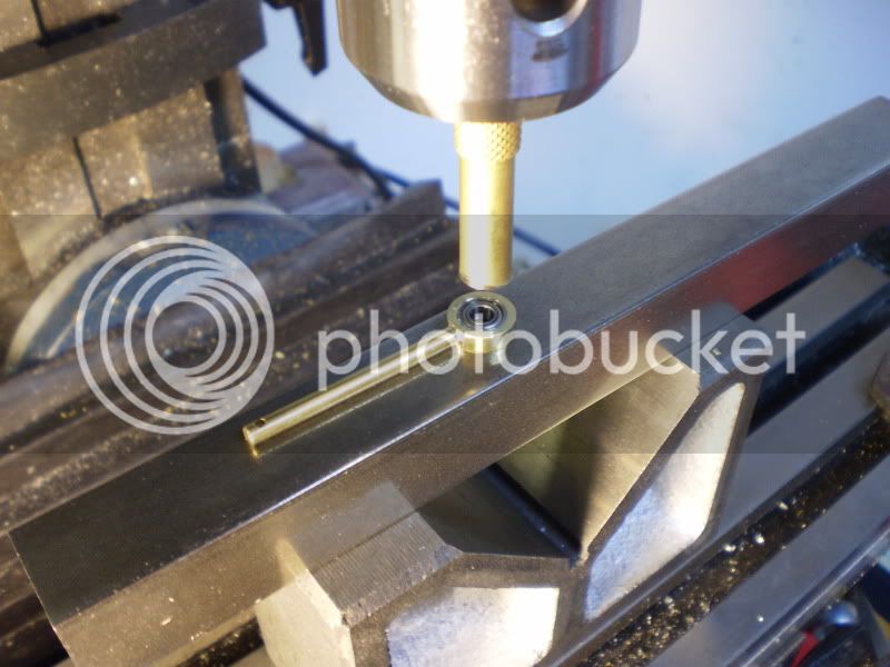
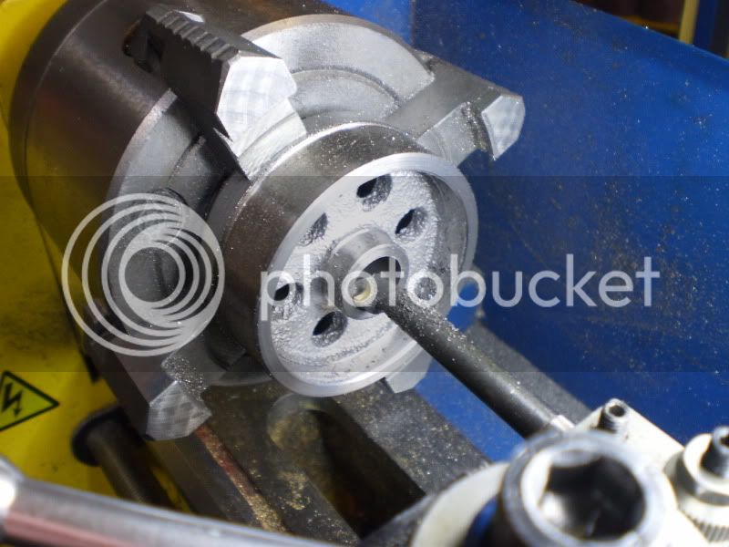
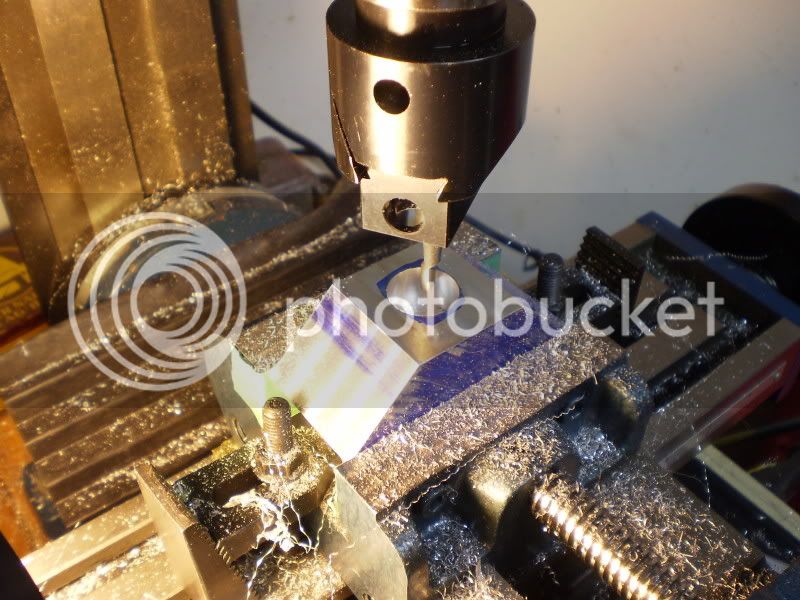
I heated the rod in the toaster oven and cooled the bearing (0.375" OD)in the deep freeze. I used a brass punch in the mill chuck to press the two together. I was surprised how easy they slid together, I was worried that I would put too much pressure on the bearing.
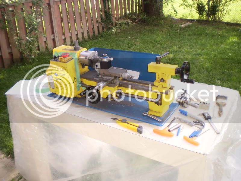
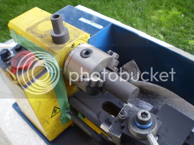
Time to make the graphite pistons. I got a 10" piece of 1.125 diameter Graphite from a friend for free, but I needed only 3/4" pistons. That meant a BIG mess was going to happen. I decided to move the operation into the back yard. I covered a table with plastic and went to work.
Here is the second piston, you can see the pile of the nasty stuff from the first one. I used those cheap carbide-tipped cutters and they cut well. I cut the pistons to within 0.010" of there final diameter and moved the operation inside for the final fit.
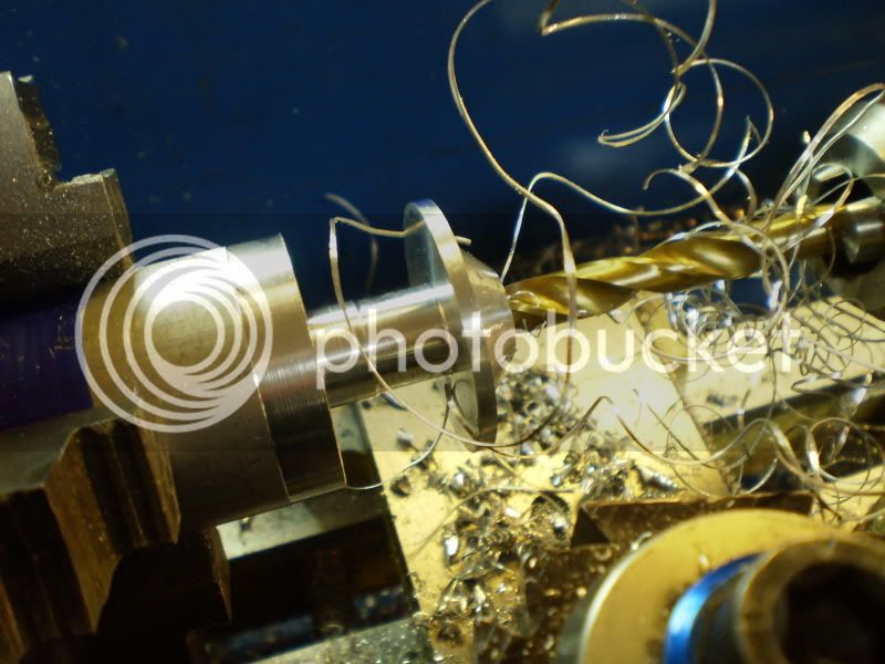
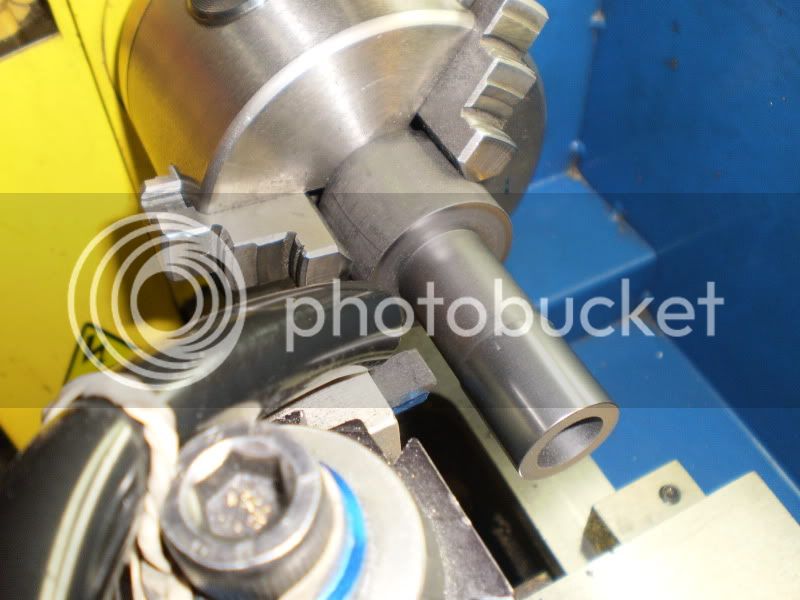
I hooked up a vacuum with a 1/2" tube at the tool post and slowly cut it down to about 0.002"
over. I then used some 1000 then 2000 grit paper until it was a tight fit in the cylinder. Next it was parted off to the correct length.
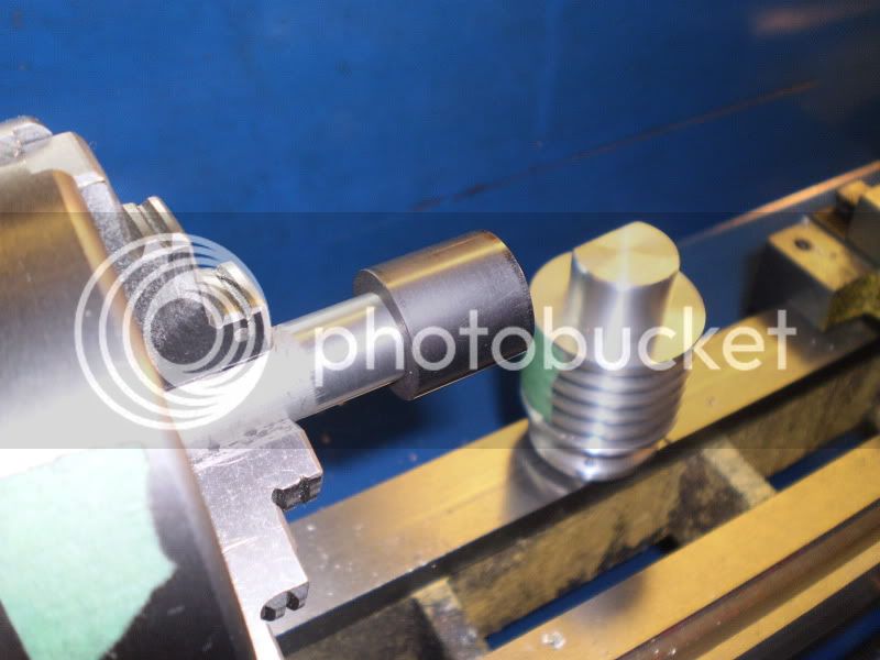
The last operation was to make a Mandel to mount the finished piston on. I used alternating 2000 grit paper and plain photo copier paper until the fit was nice and smooth.
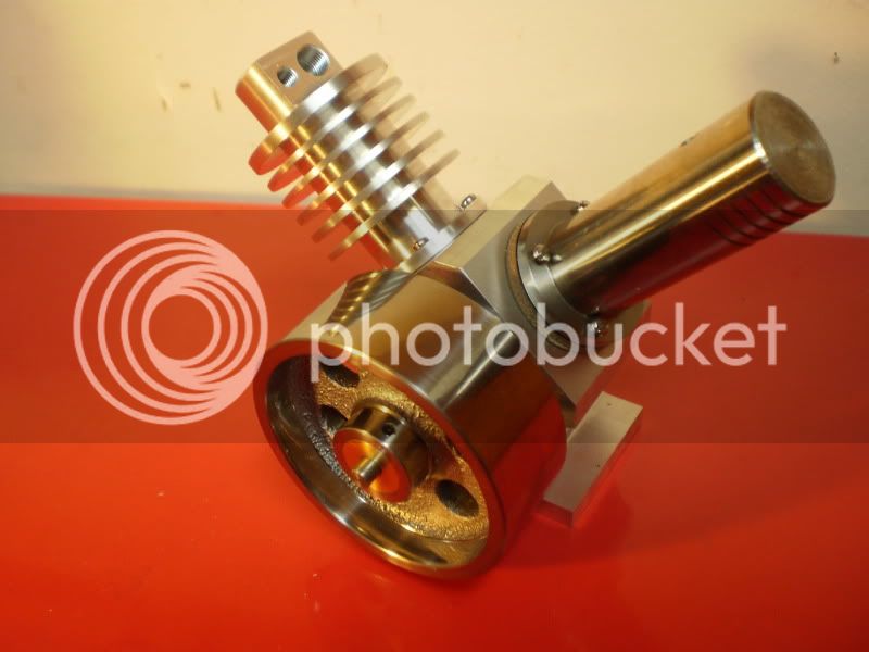
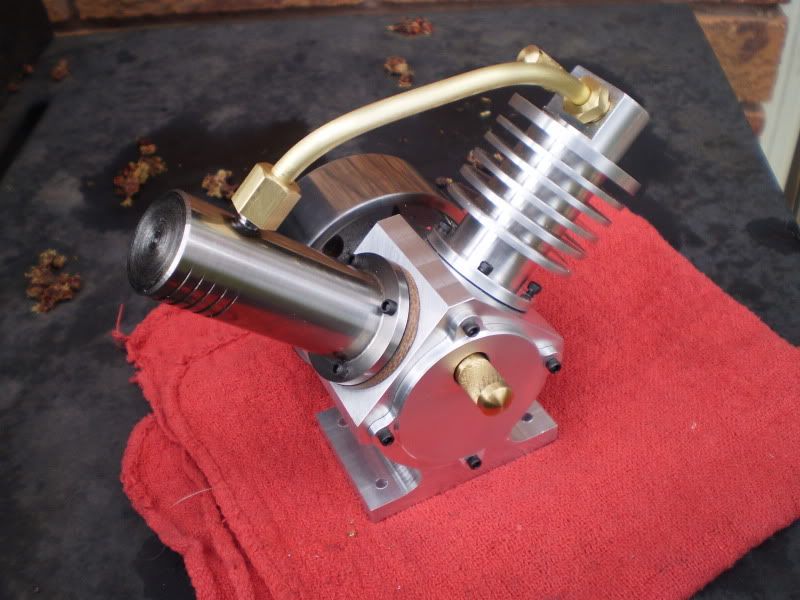
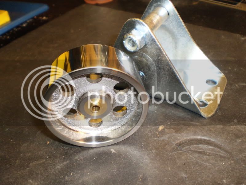
I roughly assembed the engine and it feels very smooth and if I block any of the ports there is a lot of Compression/Vacuum. I just need to make a few gaskets and do a final fit on the connecting tube and I hope to get it to run. :big:
IronHorse


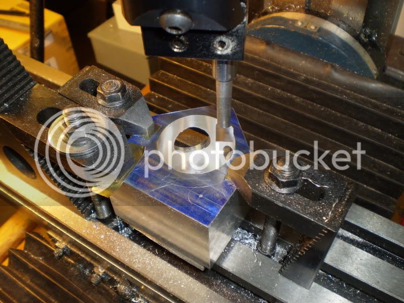
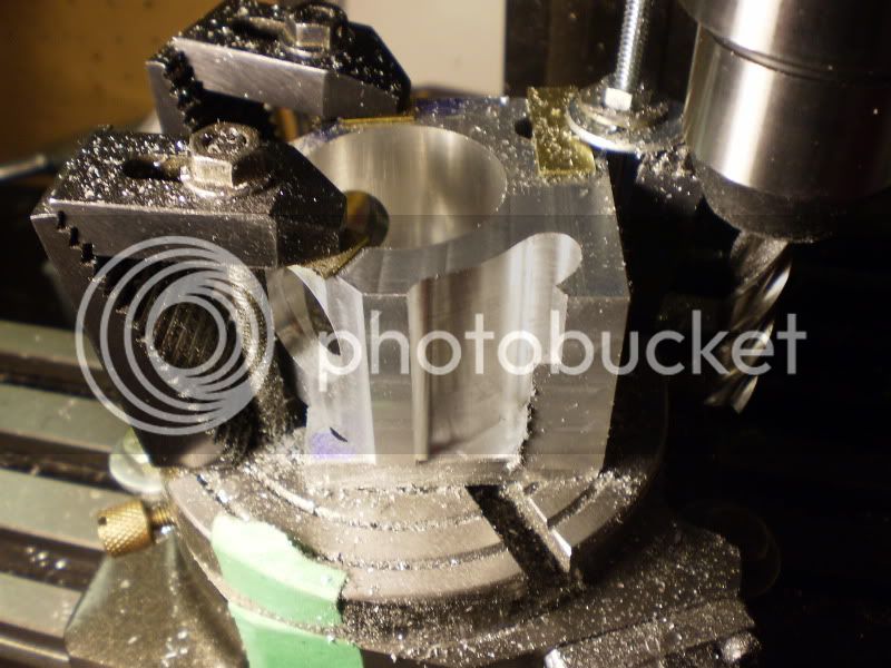
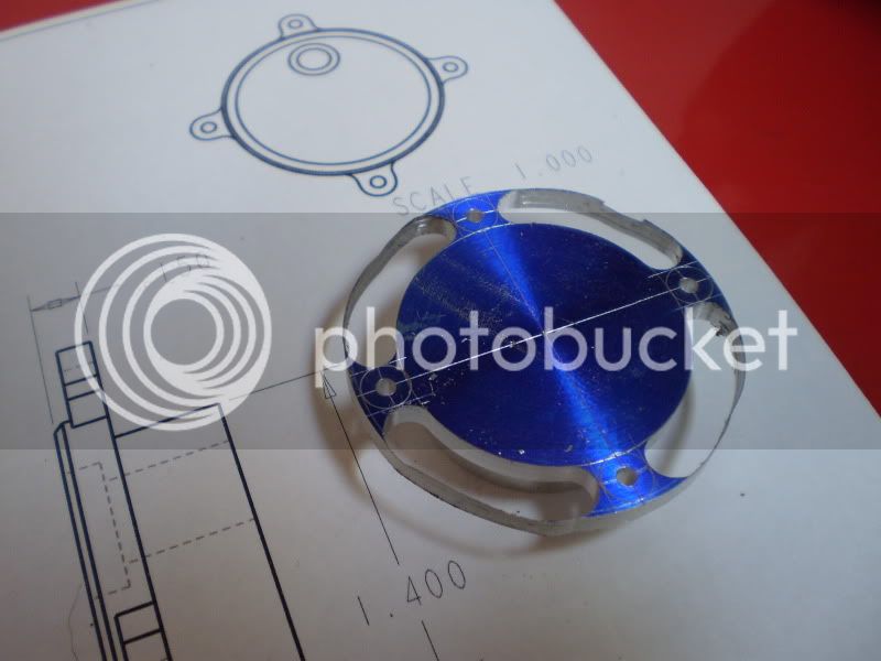
 I started with 0.015" cuts, feed in the X, rotate the table, return, feed out X. I used tape to mark both extremes on the RT during the rough out.