A vertical single 4-stroke IC engine

Home Model Engine Machinist Forum

Help Support Home Model Engine Machinist Forum:

This site may earn a commission from merchant affiliate links, including eBay, Amazon, and others.
That switch will work if you are using it with a low current transistorized ignition circuit. If you are using a standard ignition system with battery and coil, the microswitch won't handle the high current for very long.

Chuck
 
Thanks Chuck. This electrical stuff is a Brave New World for me,

Cheers,
Phil
 
After reading through this thread:

http://www.modelenginemaker.com/index.php/topic,2842.0.html

I've cleared up something that has confused me for some time. There are apparently two different air bleeds in carburetor terms.

The idle air bleed talked about in model engine carburetors is really more of a bypass that provides a small, adjustable source of air directly into the intake only when the throttle is completely closed. I believe this port is shut off as the throttle begins to open. I don't really understand why this air bleed is necessary. It seems to me the same result could be attained by just not closing the throttle as much. :confused:

The other air bleed is talked about more in full sized carburetors. It is really an adjustable port which admits air into the needle jet chamber where it premixes with the fuel. This mixture, which is controlled by the main jet needle, is then sucked into venturi where it further mixes with air from the carburetor air intake. This air bleed supposedly helps atomize the fuel, but would also, it seems to me, have an affect on the main jet mixing adjustment. I would also think the addition of this second type of air bleed might obviate the need for the first type if the throttle movement included a needle jet adjustment as well.

The carburetor described in the link above has both types of air bleed adjustment in a rather elegant arrangement fitting into a small package. It might worth trying this design to see how it works.

Chuck
 
Luc,

I did more research on Google and it does look like what I'm calling the premix air bleed is more commonly known as an emulsion tube in full size carburetors. I'm guessing the 3rd adjustment you referred to is the main jet mixture.

I agree with you that trying to make minute adjustments to main the jet mixture automatically when opening or closing the throttle is a pain. I think I'm going to try an alternate design with the main needle valve below and away from venturi and forget about trying to integrate it with the throttle actions.

Chuck
 
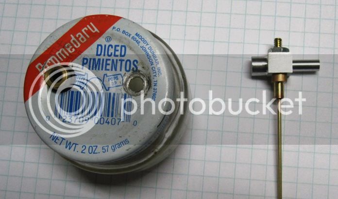
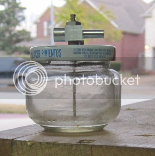
I came up with a totally new carburetor design. This one is extremely simple and easy to build. I kind of went out of the box on a few of the features, but they seem to work well. I've tried the carburetor out on my plumbing parts engine and so far I'm very pleased with the results. It idles down nicely and will rev up to nice high RPM (well, high for this engine).
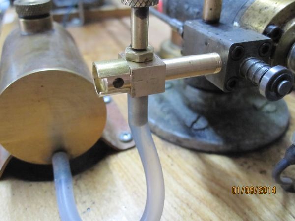
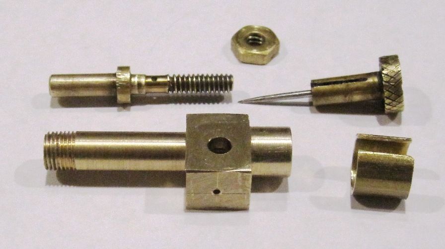
In this first picture, you can see the throttle adjustment. It is nothing more than a 5/16" ID split sleeve that rotates on the boss on the back of the carburetor body. The hole drilled into the side is the air inlet hole.

IMG_3281_zps90e00bba.jpg


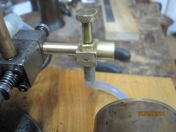
In his next picture, you can see the air bleed or premix hole. It is drilled all the way through to the center of the mixer tube just below the exit orifice that admits fuel into venturie. The entire mixer tube can be rotated left or right slightly to offset the holes in the body and tube, adjusting the amount of air that gets admitted. Different, I know, but it works well and probably won't have to be adjusted very often if at all, once tuned.

IMG_3282_zpsd6c82cf9.jpg


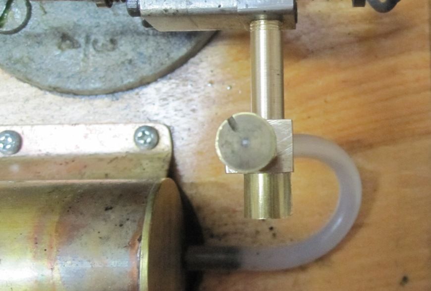
Here's a shot from the top. You can see that the mixer tube is an interference fit with the main air inlet. It protrudes slightly into the main air chamber and forms a venture. The fuel orifice is opposite and slightly above the premix or air bleed hole and faces into the air passage at a 90 degree angle.

IMG_3283_zps3364e6bc.jpg


Here is a video of the carburetor in operation on my plumbing parts engine.

[ame]http://www.youtube.com/watch?v=UaY9ROZRUqE[/ame]

I do have drawings for this but need to make some improvements to the throttle adjustment mechanism.

Chuck
 
Chuck,
Really great info for those of us new to the IC world. Thanks for taking the time to post your work. Anxiously waiting for your drawings.

Cheers,
Phil
 
Chuck--You may have just done an immense favour to all the model engine builders in the world. I look foreword to your drawings. The carb seems to work great on the engine in the video. I will use it on my opposed piston engine.---Brian
 
  • Like
Reactions: gus
Hi Chuck,

I like the new carb...seems really simple. Sometimes thinking simple (and outside of the box) yields amazing results.

You tried to explain to me how your fuel mixer works back when I was building my Ford plumbing engine...once again, how does the fuel travel up the tube into the carb? Is it just vapor that is sucked into the carb when the piston retracts?

Just curious...I would love to use this design at some point.
 
Thanks, guys, I'm pretty excited about it. Chris, the fuel is just pulled up into the carb by the vacuum of the piston on intake stroke. One think I have found helpful in start the engine, is to place a plastic tube over the vent hole in the fuel tank vent hole and blow gently until the fuel level in the fuel line reaches the carburetor. Obviously this requires a vent hole and a transparent or translucent fuel line.

Attached is a PDF file with the drawing. Let me know if you see any issues. Also, here are a couple of pictures of the carb disassembled. the first picture shows the throttle hole side of the body.

IMG_3285_zps9be247b0.jpg


And this shows the air bleed hole side.

IMG_3286_zpsc3739f6b.jpg


I'll also post the plans in the upload section.

By the way, if that brass fuel jet looks a bit worn, it's because I originally made it for my Odds n Ends hit n miss engine almost 20 years ago. I converted that engine to a vapor fuel tank some years ago and this fuel jet and needle valve have been used in any number of carburetor attempts since. It was originally designed by Phil Duclose and was used in many of his engines including the Six Cycle Odd Ball HitnMiss, the Whatzit oscillating IC engine, the vertical gearless hit n miss engine and the Topsy Turvey that I know of. Mine is an exact copy, so if you have Phil's plans for any these engines, you also have plans for my fuel jet and needle valve.

Chuck

View attachment Carburetor-Fellows.pdf
 
Last edited:
  • Like
Reactions: gus
I wanted to add this 3d model of the carb body. Note after you load it and click the activate button, you can rotate the view around by holding down the left mouse button while you drag it around. Also, if go to the little PDF menu bar and click on the down arrow in the square with the little green and blue boxes, you can change the render mode to transparent. This makes it easy to see where all the holes are and how they relate.

Chuck

View attachment Carb Body.pdf
 
  • Like
Reactions: gus
Thank you Chuck...very simple.

I would like to try this on my plumbing engine...the gravity fed fuel drip is troublesome to maintain.
 
Thank you Chuck...very simple.

I would like to try this on my plumbing engine...the gravity fed fuel drip is troublesome to maintain.

Yeah, I had read about that from some others, so that was one of the first departures I made from the Henry Ford design. If your plumbing engine is much over a 1" bore, you might want to scale this carburetor up a bit, but, again, it might not be necessary.

Chuck
 
I started on another carburetor today. This one will be for the vertical single and will be mounted on the fuel tank. Here's a picture of what I have so far.

IMG_3287_zps7cb15d3a.jpg


And, yes, I'm using a pimiento jar for the fuel tank. Clear so I can see the fuel level, no leaks, ideal as long as I don't drop it!

IMG_3289_zpscad22a25.jpg


The body is aluminum and I did make a new jet. This one is a little different. The 1/16" brass tube, which I found in my brass tubing spares box, has a .032" ID, so I just extended it all the way up into the jet tube and the needle valve will seat in it just a little below the orifice leading into the venturi.

Chuck
 
Chuck--I'm trying to model your new carburetor from your drawing, and in the left hand side of the drawing, top left corner you have the rectangular body dimensioned as 0.375" in one dimension and no width is given in the other direction. What width should it be?--Brian--
 
Last edited:
So Chuck--This is your carb in technicolour. Looks good!!! I will build it and use it on my opposed cyl engine.---Brian
 
Chuck--I'm trying to model your new carburetor from your drawing, and in the left hand side of the drawing, top left corner you have the rectangular body dimensioned as 0.375" in one dimension and no width is given in the other direction. What width should it be?--Brian--

Brian, the missing dimension is 0.500".

Thx...
Chuck
 

Latest posts

Back
Top