A vertical single 4-stroke IC engine

Home Model Engine Machinist Forum

Help Support Home Model Engine Machinist Forum:

This site may earn a commission from merchant affiliate links, including eBay, Amazon, and others.
Nice looking build, Chuck! It is certainly shaping up nicely...and yes those six spokers look better than the other one. A bit of lapping on those valves should get them to seat right in. I too have always had to break out the compound no matter how carefully I machine the valves and seats. Apparently only a few tents makes all the difference in the world. Cannot wait to hear it run.
 
Nice looking build, Chuck! It is certainly shaping up nicely...and yes those six spokers look better than the other one. A bit of lapping on those valves should get them to seat right in. I too have always had to break out the compound no matter how carefully I machine the valves and seats. Apparently only a few tents makes all the difference in the world. Cannot wait to hear it run.

Thanks! Now that the holidays are behind me, maybe I can get this thing finished.

I ran into the same problem that most people have with these little engines... I had no compression, the valves weren't sealing. So, I reset the compound on my lathe to 45 degrees and did a skim cut on both the valves with a sharp carbide insert. Then, I mounted this little jewel in the lathe.

IMG_3257_zpsb1408f11.jpg


With the same compound setting, I dressed the back of this stone to match the valve edges (faces?). The shank is 1/8" which is the same diameter as the valve stems. I inserted the shank, in turn, into each of the valve seats and, pressing lightly against the stone with my thumb, I rotated it back and forth, lifting and moving it from time to time. The valve seats were pretty thin, so it didn't take long to get a smooth, even grind all the way around. I followed this by lapping in the valves with some diamond paste diluted with 3n1 oil. I'm happy to say that the engine now has great compression, with no sign of leakage at all.

Now it's on to the carburetor!

Chuck
 
Chuck--Tell me more about the mounted point grinding tool please. What is it---Where did you get it--and how do you dress it? As for carburetors----I have to admit, I have never built a "throttle-able" carburetor. All of my engines have simple hit and miss style carburetors except for the Atkinson and the Webster, which I have mounted throttle-able model airplane carburetors on. Are you going to build a throttle-able carb for your engine? This new engine I am working on, the opposed piston engine is not one that I would want to have revving very high, so I am going to have to do something other than a simple throttle-less carb.---Brian
 
Hey Brian,

Unfortunately, I don't know where I got the stone. I think it's just aluminum oxide, maybe 100 grit. I used the same carbide insert I skimmed the valves with to dress it. I think pretty much any grind stone would work as long as it's not too coarse.

Chuck
 
Chuck I apologize for chiming in so late but I sort of lost track of this thread. About a week ago you mentioned your valves were leaking:

Both are leaking despite what I thought was an extraordinary effort to get them true
How did you establish that? Did you have "0" compression?

BTW, your twin flywheels look great. I'm about to machine a pair just like that myself.

Cheers,
Phil
 
Phil,

I could hear the air leaking past the valves when I turned the engine over by hand. And, I could tell both valves were leaking by alternately placing my finger over the intake and exhaust ports and seeing how that changed the sound. Also, I could feel the pressure against my finger.

When the engine is sealed properly, you can flip the flywheel and the piston will go part way then bounce back from the compression. If it doesn't bounce back smartly, you probably have a compression leak.

Brian, further to your comments, I haven't completely settled on a carburetor design. The one you sent pictures of is a bit large and clunky for this engine. I may have to try a new design of my own.

Chuck
 
Last edited:
Hi Chuck,

Happy New Year. Plan to build same vertical engine sometime.

Thanks, Gus. Happy New Year to you and the rest of the group!

Here is a preliminary drawing of my design for a carburetor.

Carburetor_zps37db7987.jpg


Nothing particularly new or original here other than perhaps the idea of using a slitted collar for the air bleed adjustment. Just ideas from lots of different carburetor plans I've seen.

It is going to be one of the smallest designs I've seen. The main body will be made from 3/8" square brass bar. The inlet and outlet ports will be 1/8" and the venture in the throttle barrel will funnel down to 3/32". I've never tried using an air bleed hole before so I have high hopes for this feature. The idea is to mix air in with the fuel before it reaches the jet, helping to atomize the fuel more and providing more air at idle. I've used the slitted collar before on my vapor fuel tanks to adjust the main air mixture and it works well.

The threaded shank on the throttle barrel was an idea I got from Bill Reichart's Panther Pup carburetor. It will adjust the main jet needle valve as the throttle is opened and closed.

Gonna get started on it today.

Chuck
 
Thanks for the carby plans Chuck. For my first IC engine I'm going the Ridder's vapor carb route. Eventually I'll want a carb with better control so I'll be interested to see how your design works out

Cheers,
Phil
 
The idea is to mix air in with the fuel before it reaches the jet, helping to atomize the fuel more and providing more air at idle

Hi Chuck,
unless I'm missing something the air bleed hole is not at the right place......
are your venturie tappered, and do you have the same size hole on both side of the needle???

BTW how is your CNC mill working Nice workThm:Thm:
 
Thanks Brian, Phil.

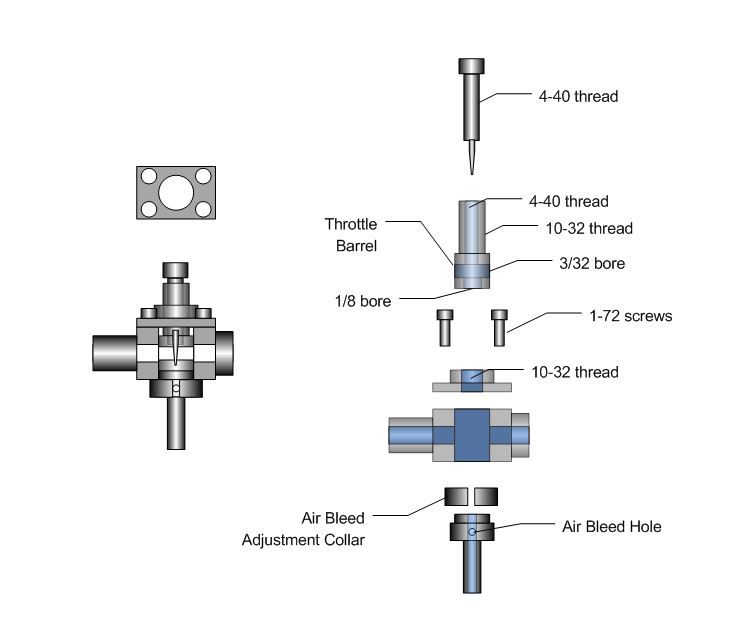
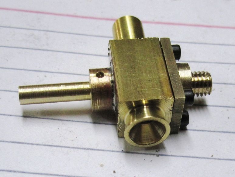
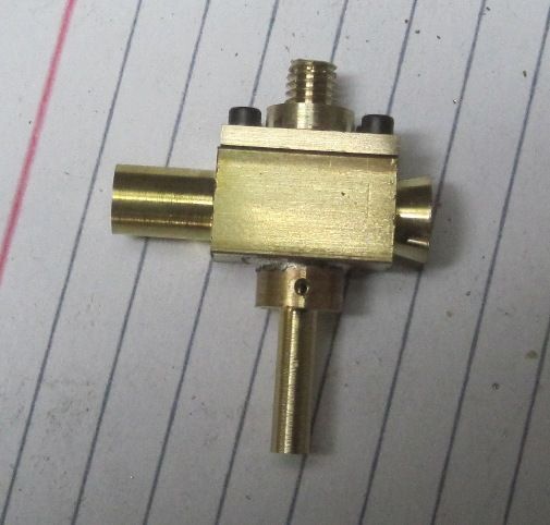
Luc, you're right, that's not the typical place you see air bleed ports in model engine carbs. I have seen at least 2 plans that have the port where I'm putting it. I think the difference is that most model carbs have an air bypass which lets a small amount of air through when the throttle is completely closed. In my design, the bleed air mixes with the fuel before it reaches the jet orifice. This supposedly helps vaporization as well as providing an additional source of air when the throttle is closed. May not work as I hope, but it's worth a try. I'd really like to come up with a simple design that works well on small engines. This seems to be a pretty problematic part for many hobbyists.

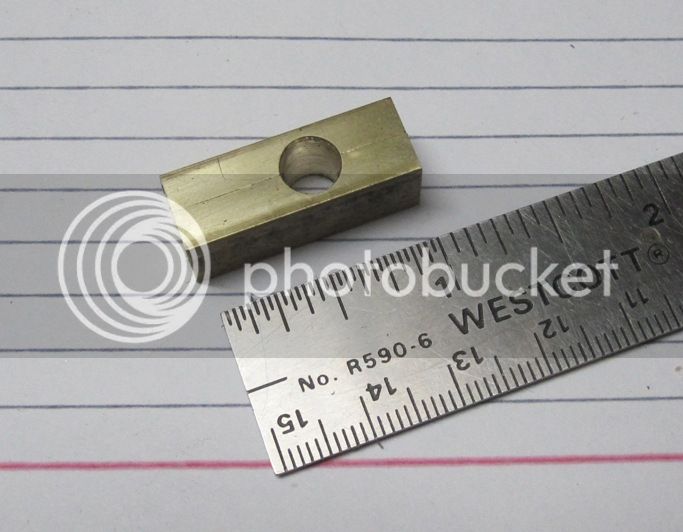
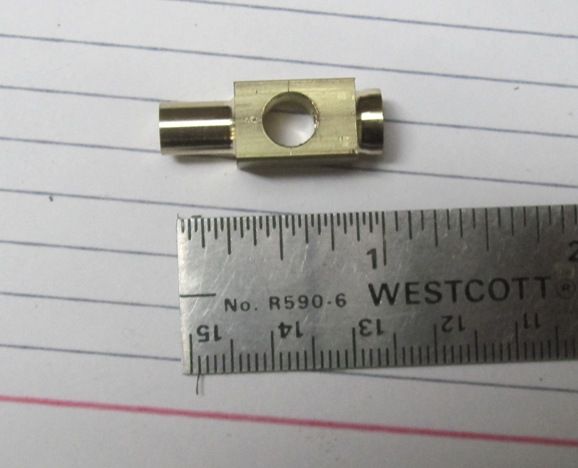
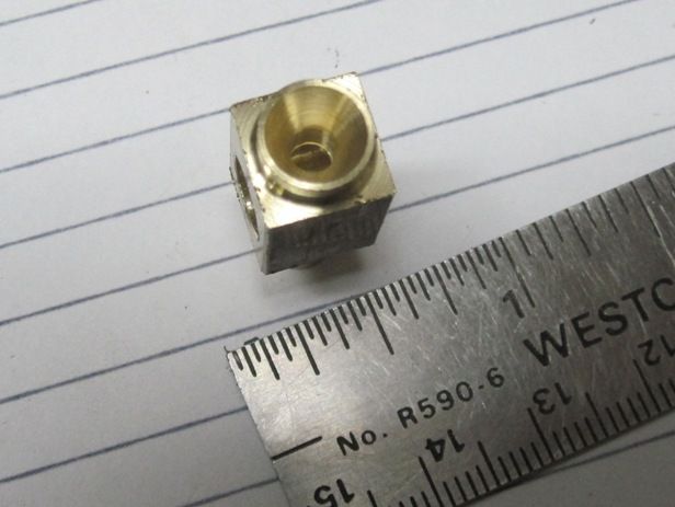
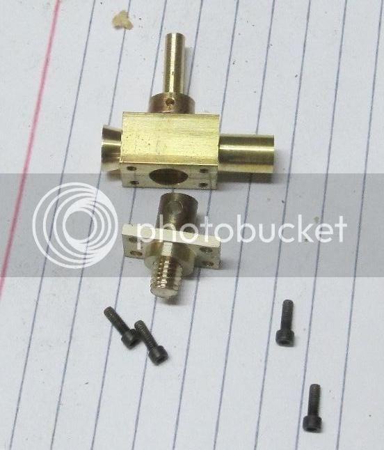
I started work today, making pieces from my drawings. I started with a piece of 3/8" square brass bar cut to a little over an inch long and drilling a 1/4" diameter cross hole for the throttle barrel.

IMG_3259_zpsfed90a9b.jpg


Next I turned down both ends, the outer end to 5/16" diameter and the engine side to 1/4" diameter. It will be threaded with a model pipe taper thread and simply screw into the head.

IMG_3260_zpsd27e56d3.jpg


I flared the outboard end and also drilled a 1/8" through from end to end.

IMG_3261_zpsb0872bdd.jpg


IMG_3262_zps760746c8.jpg


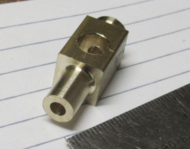
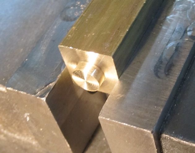
Next I made the fuel inlet pipe which has the high speed jet at the top. It also has a radially drilled air bleed hole going in through the flange.

IMG_3268_zps90e93ccf.jpg


Here is a picture of the of the fuel inlet laying in place on the carburetor body. In the finished carb, the inlet/jet will be soft soldered into the body.

IMG_3269_zps69df2fef.jpg


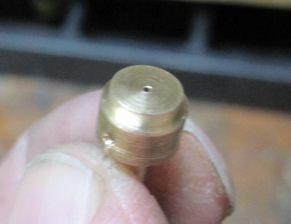
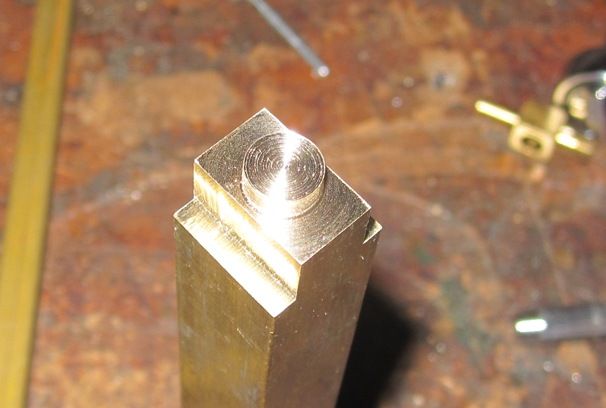
Here I'm starting on the cap which will be screwed to the top of the carburetor. It will be threaded so that turning the throttle body to open or close the throttle will cause it to pull away from or move closer to the high speed jet, making the mixture richer or leaner.

IMG_3270_zps0b1f9a54.jpg


Sometimes making these small parts is easier if you start with a rather large piece of stock. In this case, I'm using 5/8" square brass rod. The finished piece ill be 5/8" long x 3/8" wide by about 3/16" thick.

Next, I whittled down the sides to the piece is now 3/8" thick. Used the MDI function in Mach3 for the first time today to control movement of the Z-Axis. Love entering Z -0.032 and watching the end mill drop exactly .032". I think I'm going to love this conversion.

IMG_3272_zpsdc08d4ce.jpg


Here's the finished cap. I left a 1/4" boss on the bottom of the cap to register the piece on the carb body. After I drill and tap the mounting holes I will remove these boss and make it a flush fit with body.

IMG_3273_zps6d8411d0.jpg


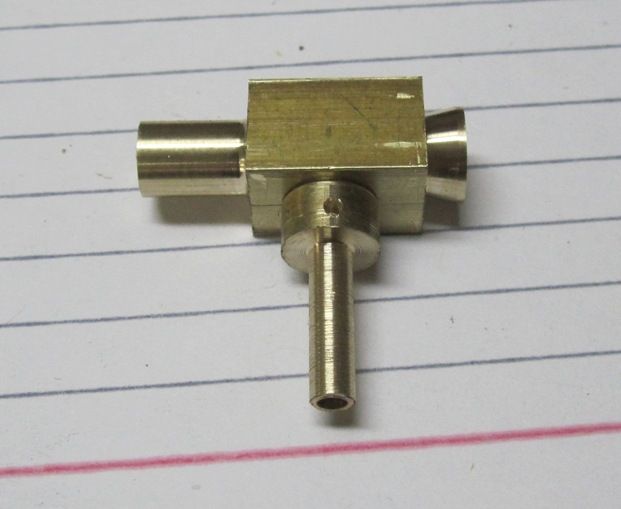
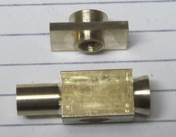
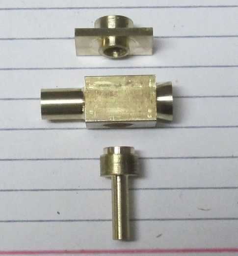
And the three pieces I finished today.

IMG_3274_zps0b05ccda.jpg


Unfortunately, I need to remake the main body to increase the length a bit. But, that went pretty fast and won't take long to make another one.

Chuck
 
Chuck,
I thought I had a set of points for the engine I'm building but they're not going to work easily. In post 39 you're showing the breaker points for this engine. Did you make those?

Cheers,
Phil
 
Chuck, Brian,

Where can I get one?

Cheers,
Phil
 
Managed to pull my self out of my recliner today and do a bit more work on the carburetor. I made a new body, drilled and tapped a few holes and made the throttle barrel.

IMG_3275_zps41f32c84.jpg


I soldered the high speed jet in place and did a test assembly.

IMG_3277_zps5c47c69d.jpg


IMG_3276_zpsbc092432.jpg


Left todo: Needle Valve, Air Bleed Adjustment Collar, Throttle Lever.

Chuck
 

Latest posts

Back
Top