A vertical single 4-stroke IC engine

Home Model Engine Machinist Forum

Help Support Home Model Engine Machinist Forum:

This site may earn a commission from merchant affiliate links, including eBay, Amazon, and others.
Thanks for the build posting Chuck! Any chance you could post a short video of the engine running with the lower compression for comparison, or is that what you've already posted?

It never fails that I learn a lot from your work - much appreciated.

Cheers Garry
 
Thanks for the build posting Chuck! Any chance you could post a short video of the engine running with the lower compression for comparison, or is that what you've already posted?

It never fails that I learn a lot from your work - much appreciated.

Cheers Garry

Thanks, Garry, I do plan to post another, longer video when I get the spark ignition installed. The glow plug ignition seems a bit erratic, sometimes trying to run backwards when I try to start it. Also, the vote is still out on how well the fuel tank mounted carb is working.

Chuck
 
Hi Chuck,
I am now torn between building your engine and Nemetts-Lynx. Most likely build your open sided engine. I like the push rods and rocker arms.
Please advise when plans are available. Great Engine.
Now in Tokyo shopping for Japanese hand tools and cutters. Its evident Gus been to TokyuHands.

IMG_0115.jpg
 
You got it, Gus! Might be a couple of weeks..

As much as I'd rather be working on improving my carburetor, I realize I have to get the spark ignition installed on this engine. I've been putting it off, probably my old, familiar fear-of-failure complex, but time to get serious.

Here is the mounting for the hall effect sensor.

IMG_3353_zps12835d53.jpg


It started life as a piece of nylon (or maybe delrin) rod, 3/4" in diameter. I cut off a 1/8" thick piece, drilled a 3/16" center hole for the camshaft to pass through and drilled and tapped a 2-56 hole to fasten it to the engine frame. I also ground off the outside edges and cut a 070" deep slot to hold the sensor with a generous dollop of 5 minute clear epoxy. Hopefully I can remove it after I've ruined the first sensor! :facepalm:

Entering unknown territory here, not at all confident that this will be an easy task!

Chuck
 
I replaced the hall sensor today with a second, also new one. No joy! :'( So, I'm officially off hall sensors and back on standard, coil ignition. I got a set of points and cam installed today.

IMG_3354_zps9df1bf95.jpg


So, if any of you guys can recommend a low profile, small set of points to use in the future, I would love to hear about them..


Here are the fixin's for my ignition box.

IMG_3355_zps97a4c06d.jpg


It's pretty much the entire assembly as it powered my original, odds n ends, hit n miss engine. The coil is a vintage 1970's, unknown make motorcycle coil. The condenser is mounted on the back of the front plate behind the switch and there were only three wires connected to the engine: ground wire to frame, hot wire to points, and high tension wire to the spark plug. I plan to get the ignition box tidied up with a case for it tomorrow. We have company showing up any minute now, but if I have time later, I may go ahead and see if I can get it started since the ignition assembly is electrically ready to go.

Chuck
 
So here is a video of the engine running on spark ignition. I haven't finished the ignition box, but I do have all the parts hooked up and operational.

[ame]http://www.youtube.com/watch?v=05Wa9mKA5Fg[/ame]

Still got some work to do on the carburetion, but the spark ignition is a decided improvement over the glow plug.

Chuck
 
Very nice Chuck. And running with the now famous Pimento Jar carby?

Cheers,
Phil
 
Thanks, Phil, yes, it is using a pimento jar for the fuel tank, but it is using a carburetor attached to the top of the tank, it's not a vapor fuel tank.

Chuck
 
Chuck--Sounds great!!! Can you come up to Barrie and hold your thumb on my engine?---Maybe tame it down some for me?---Old Chuck magic thumb!!!
 
I could sit and watch that for hours. Nice one Chuck.
Geoff
Thailand.
 
I've now built and tried 4 different variations of carburetors on this engine and am not really pleased with any of the results. The engine would run on all the carbs, but ran rough and wouldn't idle the way I wanted. I've decided to revisit some of the other parts of the engine as I think that's where some of my problems are. Most notable is the valve timing. I've always had a pretty simplistic view of cams and valve timing, figuring the intake and exhaust lobes should be 90 degrees apart, that the intake should open at top dead center and close at bottom center and the exhaust valve should open at or shortly before bottom dead center and close at or before top dead center. Well, folks, turns out it isn't quite that simple.

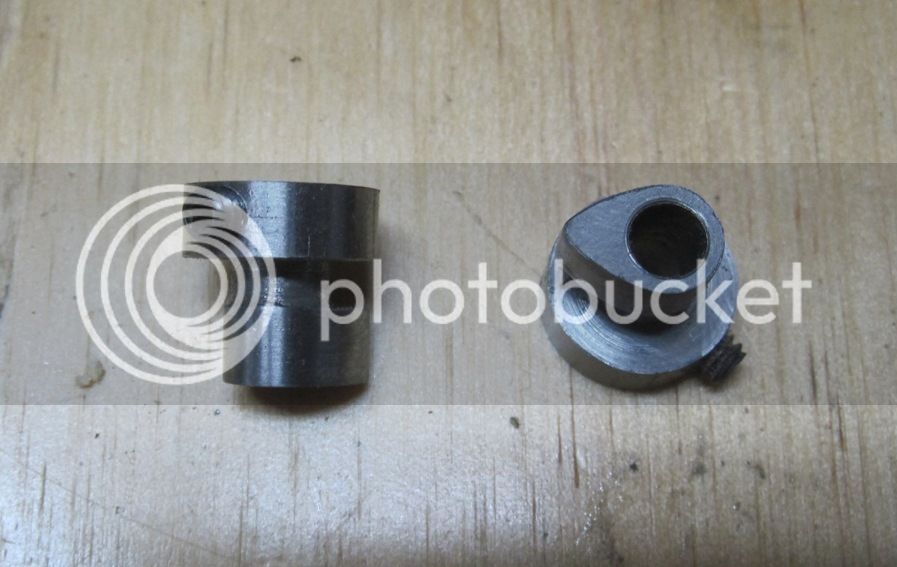
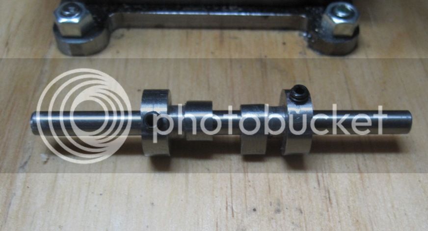
I found an article on valve timing and a series of 4 articles on cam grinding and design in my collection of Model Engine Builder. By the way, if you haven't looked through your issues of the magazine for a while, it's definitely worth revisiting. I've learned that articles in magazines don't generally coincide with what I'm working on at the moment and tend to get overlooked. It's amazing how many times I go back to older issues of magazines and find articles I had completely forgotten about or didn't even know I had. Anyway, the cam lobes should be separated by something closer to 105 degrees than 90 degrees. The intake should open from 10-25 degrees BTDC and close 40-60 ABDC. Think I'll choose 15 and 50, respectively. The exhaust valve should open from 40-60 BBDC and close 5-25 degrees BTDC. The overlap, when both valves are open, should be in the range of 10-40 degrees. A shorter overlap improves slow speed running, so I'm thinking 20 degree overlap should be good. I'm going to make the intake and exhaust lobes separately so I can adjust them independently.

By the way, I got the engine to run on Propane using two of my carburetor designs. I just removed the burner tip from my propane torch and connected it to the carburetor with a urethane tube. I had to fiddle with the propane torch control valve and the carb mixer, but I got the engine to run at least as well as it did on liquid fuel. Turns out you really don't need a demand valve as long as you don't leave the engine running unattended. But for now, the carb experiments are on hold until I get the valve timing and cam design sorted.

Chuck
 
Last edited:
I made new cams today. The intake and exhaust cams are separate so their timing can be adjusted individually. I started with 2 pieces of 1/2" drill rod, each 1/2" long and made these two spools.

IMG_3386_zps7158d178.jpg


Next I drilled and tapped the set screws, then I cut the profiles on my milling machine. I made a video and post the link once it finishes uploading to youtube.

IMG_3387_zpsa45a031d.jpg


And here's what they will look like mounted on the 3/16" carrier rod to form the finished cam.

IMG_3388_zps05fc8765.jpg


Chuck
 
Here's a video of me cutting one of the cam profiles. It's kind of a long video, so you might want to skip the middle part.

[ame]http://www.youtube.com/watch?v=IEtqETL2LXs[/ame]

Chuck
 
Aesthetics aside, (yours look much cooler) do you really think there is a difference in performance between a cam with a flat flank like I build, and the ones with a convex flank like you have there on these small low speed engines??--Brian--- Holy cow--I just watched the video--Your chuck on the rotary table is moving all over the place while you are cutting!!!
 
Last edited:
Chuck,
That's an approach I've never seen before. It's clever and shows how useful the boring head can be...it's not just for boring. I hardly ever think of it doing much more.

Cheers,
Phil
 
Aesthetics aside, (yours look much cooler) do you really think there is a difference in performance between a cam with a flat flank like I build, and the ones with a convex flank like you have there on these small low speed engines??--Brian--- Holy cow--I just watched the video--Your chuck on the rotary table is moving all over the place while you are cutting!!!

Performance wise, your flat flank gives a much quicker rise and fall than the curved flank, which is good from a performance viewpoint. However, it also puts more stress on parts since it's more like a hammer strike than a gradual lifting.

Yeah, the rotary table has a little bit of play in it that I've not been able to get rid of. I usually just use this rotary table for drilling so it's not a problem.

Chuck
 
I've been following your post and thought this might help in HSM May/June 1990 the Panther Pup build pg 31 is the carb article looks pretty nice.

Todd
 
I've been following your post and thought this might help in HSM May/June 1990 the Panther Pup build pg 31 is the carb article looks pretty nice.

Todd

Thanks, Todd, I had seen that and actually have built a close copy of it. Haven't tried it out yet.

Chuck
 
Here is yet another video as I continue looking for ways to improve carburetion for my engines. Here I've got a quick and dirty set up to run propane.

[ame]http://www.youtube.com/watch?v=EbhF-mVQGO0[/ame]

Even with this crude set up it seems to be running better than anything I've achieved with liquid fuel. Next I guess I'll start on a demand valve for it and maybe work on improving the mixer.

Chuck
 

Latest posts

Back
Top