- Joined
- Aug 25, 2007
- Messages
- 3,890
- Reaction score
- 715
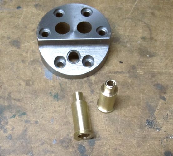
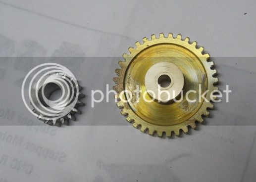
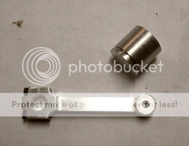
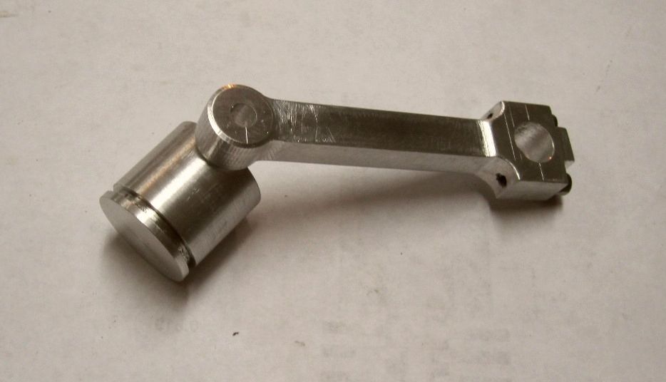
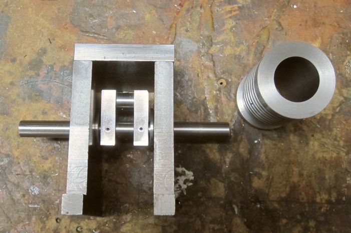
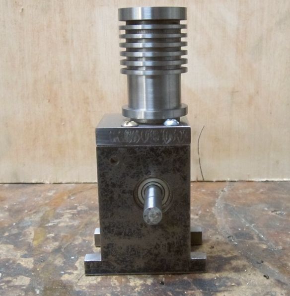
Although this engine shares some similarities with other vertical single engines, such as the Upshur and one built by Randall Cox, I'm calling this my own design since it has significant differences from the others. It will be air cooled and have a bore and stroke of 7/8" x 1.25". It will be throttled, not hit n miss.
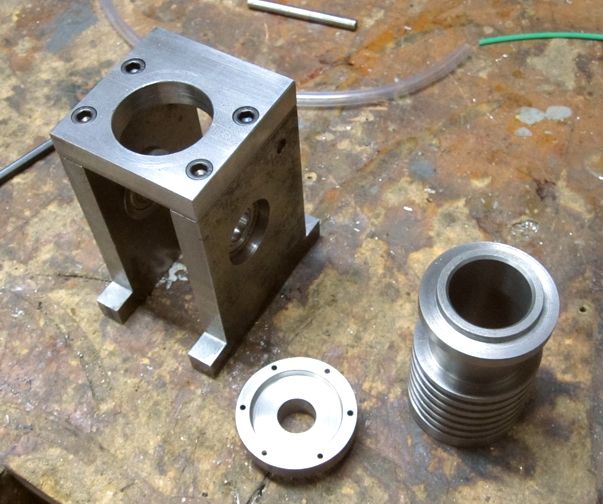
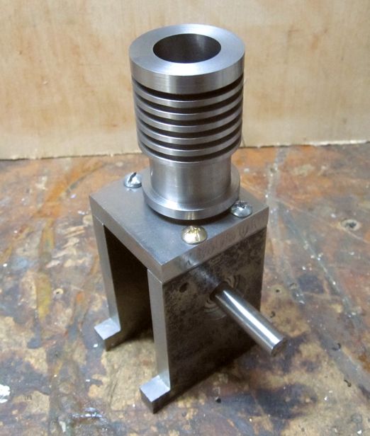
I salvaged two vertical pieces I had from a previous project that never came to fruition (sound familiar?). There were two 10-24 tapped holes in the top of each one and I had to make horizontal piece that fit across the top to fasten the two vertical pieces together. Trying to drill holes in a top piece that align with threaded holes on the bottom part has never been a strong suit of mine.
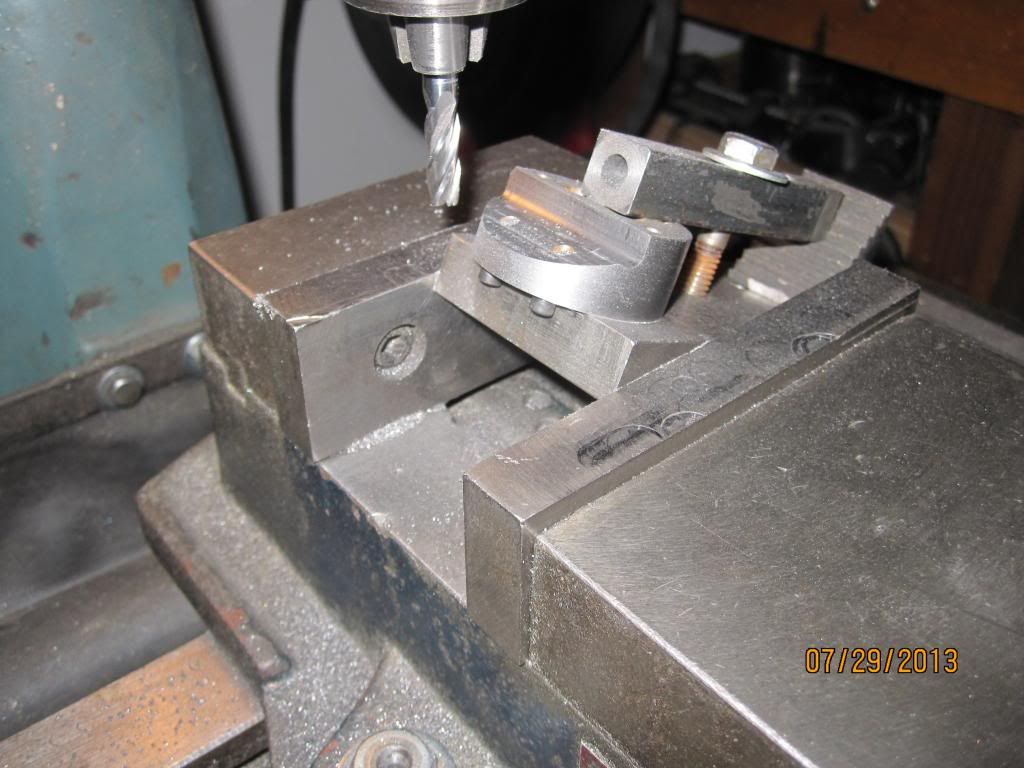
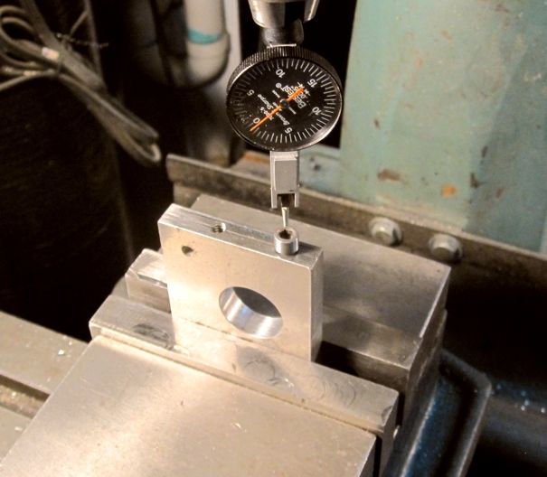
I first found a socket head cap screw that was the right length and thread size and mounted the threaded end in the 3 jaw chuck on my mini lathe. Then I cleaned up the head of the screw so it was concentric with the threaded end. After inserting the screw into the hole I wanted to match, I mounted the piece vertically in my milling vice, using a stop to precisely locate the edge from the side of the vice jaw. I then used a DTI to exactly center the screw head under the mill / drill spindle...
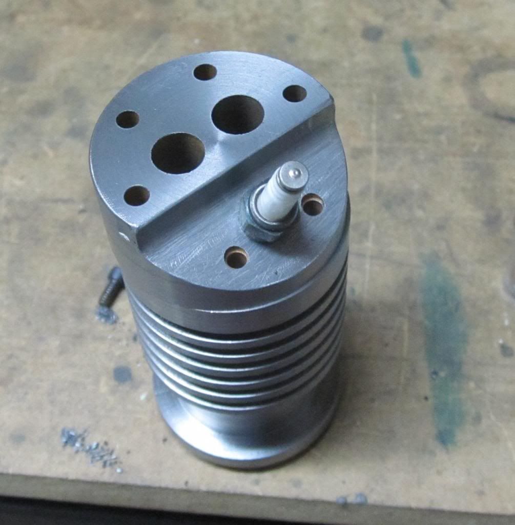
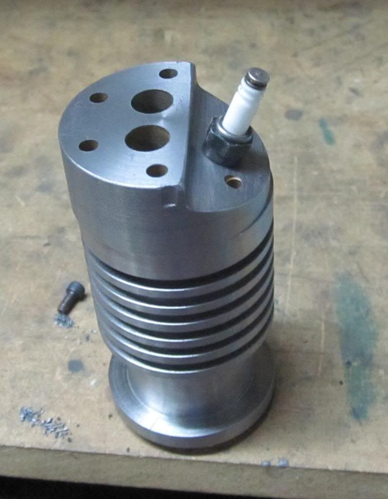
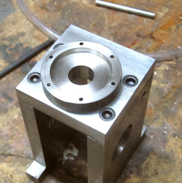
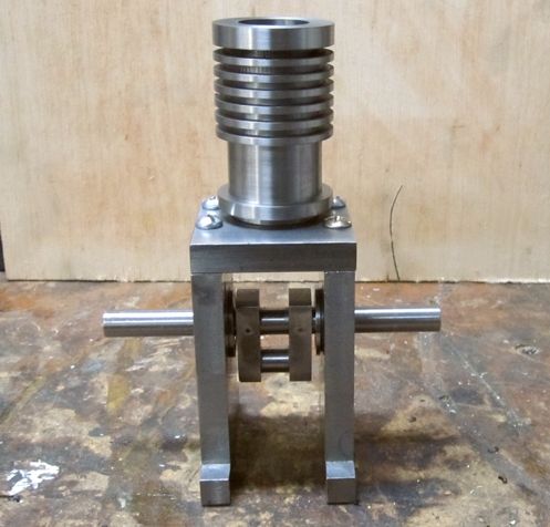
Then, I removed the vertical piece and inserted the blank top in the vice with matching back edge against the vice jaw and the end against the stop on the side so it was the same distance from the side of the vice jaw. I repeated the process for each of the 4 screw holes and here is the result...
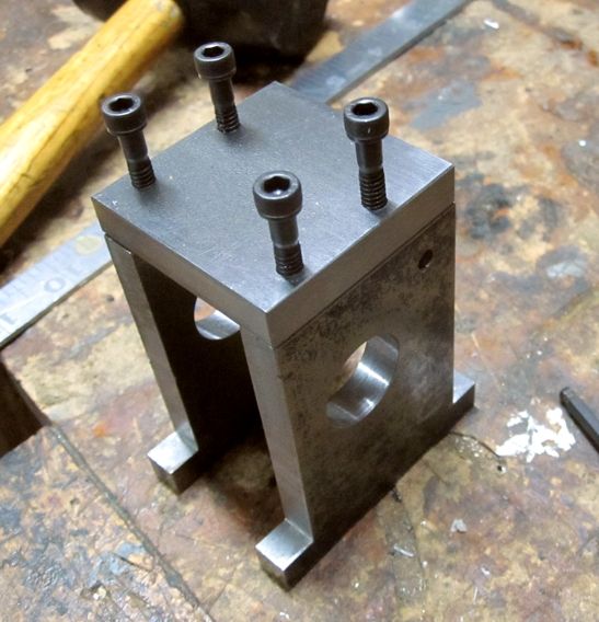
The result is as near perfect as I've ever achieved!
I salvaged two vertical pieces I had from a previous project that never came to fruition (sound familiar?). There were two 10-24 tapped holes in the top of each one and I had to make horizontal piece that fit across the top to fasten the two vertical pieces together. Trying to drill holes in a top piece that align with threaded holes on the bottom part has never been a strong suit of mine.
I first found a socket head cap screw that was the right length and thread size and mounted the threaded end in the 3 jaw chuck on my mini lathe. Then I cleaned up the head of the screw so it was concentric with the threaded end. After inserting the screw into the hole I wanted to match, I mounted the piece vertically in my milling vice, using a stop to precisely locate the edge from the side of the vice jaw. I then used a DTI to exactly center the screw head under the mill / drill spindle...
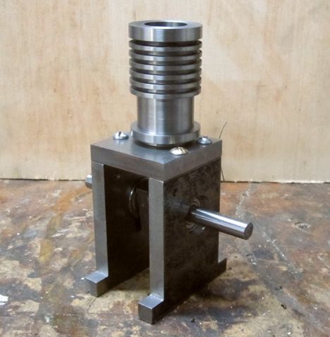
Then, I removed the vertical piece and inserted the blank top in the vice with matching back edge against the vice jaw and the end against the stop on the side so it was the same distance from the side of the vice jaw. I repeated the process for each of the 4 screw holes and here is the result...
The result is as near perfect as I've ever achieved!
")