A Two Cylinder Steam Engine

Home Model Engine Machinist Forum

Help Support Home Model Engine Machinist Forum:

This site may earn a commission from merchant affiliate links, including eBay, Amazon, and others.
Hey Gerry have you started posting a build log of your Elmer #11?

No, not yet. I am planing on making the cylinders today, taking some photos as I go. I have the base, crankcase and engine foot made. I will maybe start it this afternoon after getting my ducks in a row to begin the log. Upload photos, begin working on the text, etc. I would like to create the text in word then copy to the forum in segments as I go I think.

So far your build looks amazing. Looking forward to your progress on the cylinders.

Gerry
 
[SIZE=+2]THE CYLINDER ASSEMBLY - 2. Making all the Bolts[/SIZE]

INTRODUCTION

In my previous post I referred to making the set of bolts for the two cylinders as an "irksome chore". This is perhaps a bit unfair in the sense that it becomes so because there are 40 of the darn things and not because the steps required for each bolt are boring. It would be equally or even more irksome to make 40 cylinders or 40 flywheels! So on reflection I think that the process of converting over 70cm of 5mm steel bar into 40 M2 bolts may hold some interest for some members and so will report it in this post like any other step in the build of my engine.

DESIGN CONSIDERATIONS

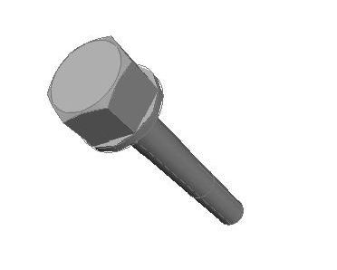
For both asthetic and practical reasons these 40 screws are identical except for a single parameter namely the length of the shank (L) as shown in the drawing extracts below.
CYABolts00Dwg_zpse757b0d8.jpg

CYABolts00Model_zpsc2950c39.jpg


So the bolts are all have 2mm diameter shanks threaded for a length of 5.5mm of which only 4mm of thread are intended to enter into the corresponding threaded hole. The bolts all have the same head which is a hexagon with 4mm across the flats (F) and with a circular base, height 0.5mm, of diameter 4.62mm (V) which is the distance between opposite vertices of the hexagon obtained from the formula V = F / cos(30).


The 20 bolts required for each of the two Cylinder Assemblies are listed below:
  • 6 bolts with L = 7mm for fixing the Cylinder Top Cover to the Cylinder Unit.
  • 5 bolts with L = 10mm and 1 bolt with L = 15mm for fixing the Cylinder Bottom Cover and the Cylinder Unit itself to the Vertical Structure.
  • 8 bolts with L = 19mm for fixing the Steam Chest Cover and the Steam Chest to the Cyinder Unit.
BUILD APPROACH

The bolts were machined from a 5mm diameter bar of mild steel. I was not able to discover the composition of this steel but judging from the way it behaved during machining I would guess that is lead free and with a carbon content of around 0.3%.

The process I use to make nuts and bolts is of course influenced by the tools I have. If I were making a single bolt then the basic sequence of steps I would use for making it would be more or less to make the shank, prepare a cylinder for the head, cut the bolt off the bar and then hold the bolt by the shank to make its head.


Here is this process described in more detail.
  1. Make the shank and prepare the cylinder for the head
    • Hold the raw bar in the chuck with about L + 6 mm protruding from the jaws.
    • Use a knife tool to face off the end.
    • Use a knife tool to turn the first 7mm of the shank to the final diameter of about 0.02 mm under 2mm.
    • Thread the first 5.5mm of the shank holding the M2 die in some sort of tailstock die guide.
    • For bolts with shanks longer than 7 mm, use a knife tool to complete turning the shanks in one or two sections not longer that 6mm. This is necessary to avoid excessive flexing of the rather thin shank even when the tool is sharp.
    • Use the knife tool to turn to a diameter of 4.62 mm a cylinder 4.5mm long for the head.
    • Manually cut the screw off the bar leaving the head section with a length of at least 3.5mm.
  2. Make the head
    • Gently hold the bolt in the 3-jaw by the shank with the head cylinder pressed up against the jaws.
    • Face off the end so that the head has the required finished length of 3mm.
    • Make the flats of the hexagon with a hand file, using my File Guide [thread]19573[/thread]and using the lathe's Gear Train to position the angle of the lathe spindle.
    • Use a metric threading tool to turn the 30 degree bevel on the edge at the end of the head.

So, on this basis, what is a good process for making 40 bolts? I had to choose between two alternatives.
  • Make the bolts one by one, doing for each the above process. With this option I would do a lot of setting up and measuring to ensure that all the bolts turn out with the correct dimensions.
  • Do each setup once only and for each apply the corresponding step of the process to all 40 bolts. With this option I would do a lot of bolt mounting and dismounting but, with proper use of a carriage stop, I would do the setting up and most of the measuring only once.

I plumped for the second approach. So I applied each of the following four steps to all 40 bolts.
  1. For each bolt, make the shank, prepare the head cylinder, cut the bolt off the bar. During this process the Knife tool was sharpened after every three bolts.
  2. For each bolt, face off the end of the head using the carriage stop to ensure that all heads have the same length.
  3. For each bolt file the flats of the hexagon section of the head, again using the carriage stop to ensure that the circular bases all have the same length.
  4. For all bolts machine the 30 degree bevel again using the carriage stop to ensure that all bevels have the same depth.
There was a problem in this approach owing to the fact that my 3-jaw self centering chuck cannot grip diameters below 3mm and so cannot grip the 2mm shanks of the bolts. To make a single bolt I would solve this problem simply by holding a smaller chuck in the 3-jaw. But this is inappropriate when using the same setup for many bolts because the teeth of this smaller chuck dont close in a plane orthogonal to the axis; when closing the chuck, its teeth move foreward along the axis as well as closing towards the axis. This would have made the use of the carriage stop inaccurate for the last three steps of the process. So I solved the problem by making a small mild steel split sleeve which has a 2mm bore, a 3.4mm external diameter and is 5mm long. The big chuck squeezes the sleeve which in turn squeezes the bolt shank. It is important that the external diameter of the sleeve is a good bit less that the diameter of the head base, and so I could still press the head bases up against the chuck jaws to ensure the correct position of the bolt along the lathe axis. It worked fine.

BUILD LOG

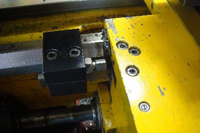
This is the carriage stop which came with the lathe when I bought it and is worth it's weight in gold! Some day I'm going to make a second one to use on the other side of the carriage for when I'm machining rightwards towards a shoulder.
CYABolts01CarriageStop_zpsf468c262.jpg


Step 1: Shank and Head Cylinder

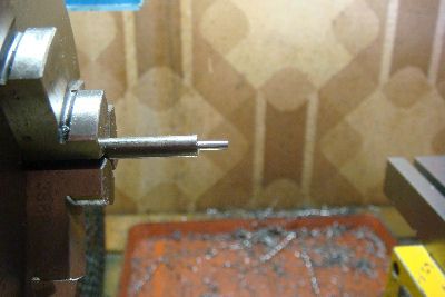
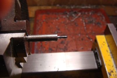
Here is a bit of 5mm raw bar sticking out of the chuck ready to make a bolt with a 19mm shank.
CYABolts00RawBar_zps13332db7.jpg


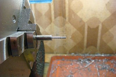
Here is the first 7mm of shank turned to a diameter of 1.98mm.
CYABolts02First7mmTurned_zps6e919c18.jpg


Here is this first 7mm of shank being threaded M2 with a tailstock guide for the die.
CYABolts03First7mmThreading_zps04ebf959.jpg


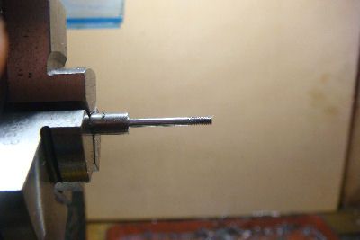
Here is this first 7mm of shank with about 5,5mm of M2 thread.
CYABolts04First7mmThreaded_zpsbb177729.jpg


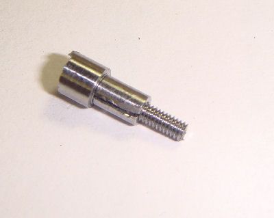
Here is the bolt with a further 6mm of shank and then with the completed shank with a total length of 19mm.
CYABolts05Second7mm_zpsd92bfa3e.jpg

CYABolts06Third7mm_zpsfada713b.jpg


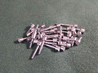
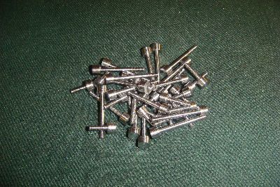
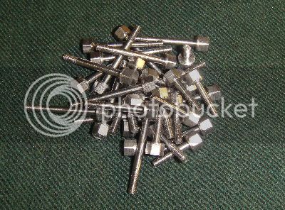
Here are all 40 bolts at the end of this first step.
CYABolts07PhaseIdone_zps753568be.jpg


Step 2: Face Off the Head

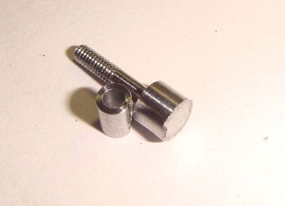
The next three photos show the small sleeve with a 7mm bolt next to it, the bolt inserted into the sleeve and finally the bolt held in chuck via the sleeve.
CYABolts08SleeveAndClient1_zps53360864.jpg

CYABolts08SleeveAndClient2_zps20f48b9e.jpg

CYABolts08SleeveAndClient3_zps1bb4d559.jpg


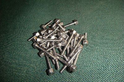
Here are all 40 bolts at the end of the second step ie with the heads faced off to the final length of 3mm.
CYABolts09Phase2Done_zps0ffcbaae.jpg


Step 3: File the Hexagon Section of the Head

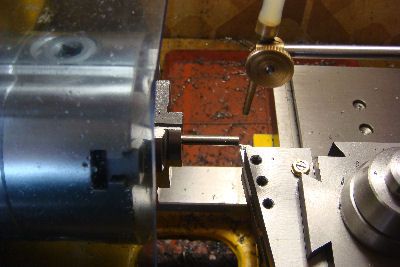
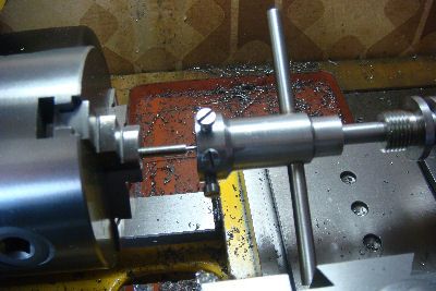
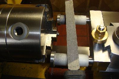
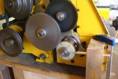
The next two photos show the setup with the Filing Guide for filing the flats of the hexagon sections of the heads and the way I use the lathe's gear train to index the angular position of the spindle. The train is set up to multiply by 4 and the final white gear in the train has 60 teeth. Hence for each full revolution of the lathe spindle 240 teeth pass the horizontal indexing rod held uin the block of wood. So to rotate the spindle by one sixth of a rotation I must let 40 teeth go past the index rod. With the help of the pencil marks at every tenth tooth of the gear it's a piece of cake!
Note that the carriage stop is in position to ensure that the limit to leftwise horizontal motion of the file is always at the same distance from the chuck jaws.
CYABolts10HexFilingSetup_zps18b5215f.jpg

CYABolts11HexFilingIndexing_zps0836e22e.jpg


Here is a single bolt with the hexagonal section of its head filed.
CYABolts12FirstHexDone_zps337d204a.jpg


Here are all 40 bolts at the end of the third step ie with the heads faced off to the final length.
CYABolts13Phase3Done_zps90b8e4ee.jpg


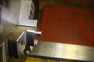
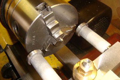
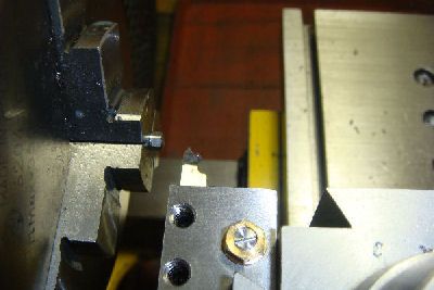
Step 4: Bevel the Edge of the Head Section of the Head

This photo shows the setup for beveling the Egge of he Hex Section. The carriage stop is in position to ensure that the limit to leftwise motion of the tool is always at the same distance from the chuck jaws.
CYABolts14SetupForBeveling_zps30aab117.jpg


And here finally are all 40 bolts finally finished.
CYABolts15Phase4Done_zps63a48542.jpg


Total shop time for the job was roughly 20 hours: an average of 30 minutes per bolt. Something tells me that there must be a quicker way!

WHAT'S NEXT?

Now I can start of the two Cylinder Units. After all my recent handling of steel I'm looking foreward to machining brass.
 
Hi,

Thanks for the drawings, Nice thread btw.
Would it be possible to convert the complete assembly to stp or step format and post it on the forum please.
I like to walk through. An inside view is always very impressive...;)

I think this engine will be a candidate for a school project next year.

Thanks in advance.

Chris
 
Hello Chris,
I would like to oblige but you'll have to help me. I didn't know of the stp format but Google sorted that out. Unfortunately
my CAD software uses dwg format and doesn't include the stp format amoung its SaveAs or Export formats. With Google I failed to find a dwg to stp converter. Can you point me in the right direction?
 
Ian,

STEP format is the most widely used data exchange form
It is possible your CAD software does not allow to convert to stp or step format.
But seeing your 3D images I thought you were using one of the latest CAD software.
The older versions of AutoCAD (for instance) does not allow to export to stp or step.

See also : http://www.fileinfo.com/extension/stp

Thanks,

Chris
 
Hi Ian,
That's pretty cool how you use your change gears to help you index your head. I like your file jig too.
Gerry
 
Total shop time for the job was roughly 20 hours: an average of 30 minutes per bolt. Something tells me that there must be a quicker way!

Hi Ian,

My compliments on the very fine build thread. This serves as an example of how to write a build thread.

Well laid out, copiously illustrated with clear sharp photos, and complete the plans. I particularly appreciate that your laid out the build process without skipping any critical processes or omitting photos to save time. This ensures that novices such as myself can complete the same build with little difficulty. No matter if it is now or 3 years from now when you may not be around to answer questions.

If you can get a stp file I too would appreciate it.

finally, I am not sure the size of the bolts you made, but wouldn't it help if they were machined from hex rod of the appropriate size saving the need for the indexing and filing?
 
Gerry, Chris and Torontobuilder. Thank you all for your generous compliments.

Chris. You are right, my CAD SW is over five years old; I have been putting off upgrading because I didn't feel the need for it and to avoid the inevitable and usually unreasonable investment of time required! Now I have a reason to upgrade so I will move a CAD update at least onto my table if not directly onto my plate!

Torontobuilder. Yes starting from hex would save about 10 minutes per screw. Back in the 50s in South Africa I once ordered mild steel hex rod from the UK to make the bolts for steam engines. Delivery took six weeks by sea! Now, here in Rome I have found hex rod in brass and stainless steel but not in mild steel. It is available from the UK in both imperial and metric sizes in 12 inch lengths at a certain price. But I decided to make the bolts from round bar because I wanted that round base below the hex section both aethetically and to protect the brass surfaces under the heads from being scratched by the socket spanner.
 
Ian,

Off topic ....

Depending on how often you'll need 3D CAD software I would advice learning it. Once you master it you'll gain lots of time
There are a few free version to be found out there.

I must admit, for me making all these drawings for the projects I'm building is part of the fun. Addicted is the correct word here I think...;)

Chris
 
Torontobuilder. Yes starting from hex would save about 10 minutes per screw.

I wondered how much time a collet block would have saved you when I first read this thread. Only because I found out I can get a 5c collet spindle for my lathe, so have been considering investing in a set of blocks for jobs like this where I wanted a hex head on some round stock. I was not sure if you would hold the screw in the collet or screw it into some round stock held by a collet given the small size.
 
Chris
Depending on how often you'll need 3D CAD software I would advice learning it. Once you master it you'll gain lots of time
There are a few free version to be found out there.
I must admit, for me making all these drawings for the projects I'm building is part of the fun. Addicted is the correct word here I think
I have been using 3D CAD software for many years now and thoroughly agree that the effort to learn 3D modelling and the extraction of 2D drawings from the 3D model is more than worth while both for the time it saves when building and because it is fun! What I was trying to say in my reply to you was that, in my experience, the effort to install and learn an upgrade to this or any other software tool often seems unreasonable.
 
Hi RodW.
I wondered how much time a collet block would have saved you when I first read this thread.
I dont have collets on my lathe and have been meaning to look for some and of course, to weigh the cost. However in the case of my screws I dont see why I would have saved time with respect to using a 3-jaw self-centering chuck. In my mind collets contribute accuracy rather than speed.

I was not sure if you would hold the screw in the collet or screw it into some round stock held by a collet given the small size.
I think that some sort of sleeve, made in a material softer than the bolts, is advisable to protect both shank and thread of the bolt from the very hard jaws of a chuck or collet. I decided not to thread the sleeve both because I wanted the same sleeve to work for bolts of different lengths and because, especially for the longer bolts, I didn't like the idea of the spindle torque being transmitted from the thread to the head via the entire length of the bolt's slim shank. I preferred to make a short sleeve which squeezed the bolt's shank right up next to the head.
 
... I decided to make the bolts from round bar because I wanted that round base below the hex section both aethetically and to protect the brass surfaces under the heads from being scratched by the socket spanner.


Ah, I see the logic, I didn't notice the flange on your bolt heads and hadn't yet read about that in the details.

I can appreciate the desire to add those little details... time is of little consequence when compared to getting all the details right on a showpiece. That and the process is much of the enjoyment so whats a few extra hours.

Myself, if I build this to actually steam then I'd use hex and washers... just to get to the actual steaming quicker. But it is good to see hwo other people think when designing and building.
 
Hi,
in the post #16 you write
" Since the Eccentric which moves the valve is fixed to the Shaft at 90 degrees with respect to the crank pin which moves the Piston,..."
but it is usually not so, you have to add some lap on the valve and advance the setting of the eccentric accordingly, to allow steam expansion and greatly improve running with steam.

I have read the whole built, wow, amazing thread, you do not spare your work, and very elegant design too, many thanks for sharing.

Zephyrin
 
One of the most detailed build logs I have seen. Beautiful drawings and complete descriptions.
Thanks for sharing your ideas and your work with us.
Mike
 
Hi Zephyrin.

Yes indeed! Thank you very much for this stimulus and for your compliments. As stated in it's preamble, the paragraph you mention wanted to be a brief explanation of the Slide Valve for folk meeting it for the first time. However I should have mentioned the theme of efficiency which you have touched. So here goes, once again for the same audience and again trying comunicate principles and issues. I'm still trying to be brief but the subject is not that simple.

As you say, one can improve the performance efficiency under live steam by adjusting both the dimension of steam ports and/or slide valve and the angle of the eccentric. The objective is to reduce the fraction of the cycle for which live steam is connected to the piston from the full half cycle (0 to 180 degrees) to somewhat less (e.g. 0 to 90) so that for the rest of the half cycle the push is coming from the expansion of the steam already in the cylinder. At the end of the stroke the steam pressure will have fallen and so less energy will be thrown away through the exhaust port. In our example, if the live steam pressure is 5 atmospheres above atmpspheric (=6 absolute) then, at the end of the stroke, the pressure will have halved to roughly 3 atmospheres absolute (= 2 atmospheres above atmospheric).

One would like to keep the exhaust connection open from 180 degrees to 360 degrees. However, with a single Eccentric moving a single Slide Valve which moves across fixed Steam Ports, the angle of maximum opening of the exhaust connection must necessarily be 180 degrees from the angle of maximum opening of the live steam connection. These two connections can have different durations but their centers must be diametrically opposite. So if we insist that the live steam be admitted to the cylinder from 0 to 90 degrees (center 45 degrees) then the center of the exhaust connection must be 225 degrees which seems embarassing because if the connection were to open at 180 degrees then it would close at 270 degrees ie 90 degrees too early.

In practice however this is less embarassing than it may seem at first sight, because once the exhaust connection opens, the pressure in the cylinder falls rapidly to atmospheric pressure (assuming that the used steam exhausts into the atmosphere). The premature closing of the exhaust connection results in a back pressure building up in the cylinder which, in our example, would be of the order of one atmosphere above atmospheric when the piston gets to 360 degrees.

One can seek a better compromise by trying to move the angle of maximum connection nearer to the 90 degrees we started from. So instead of opening the inlet from 0 to 90 we could open it from 20 to 90 remembering that at the top of its stroke the piston is not able to transfer torque to the crank shaft very well. This moves the inlet axis center foreward by 10 to 55 degrees and so the exhaust axis center moves foreward to 235 and hence the exhaust could still open at 180 but would close at 290 instead of 270.

How do we adjust the Valve System to be more efficient?

Firstly the angle of the Eccentric must be set so that the throw of the eccentric is vertical at the two points of maximum connection. In our example, if we wish the maximum input connection to the top of the cylinder to occur when the crank pin is at 55 degrees then at that point the eccentric must be at 180 degrees ie at 125 degrees ahead of the crank pin. This is 35 degrees ahead of the 90 degree position for the inefficient valve system.

Secondly we must modify the Sllde Valve itself to reduce the fraction of the cycle for which the connections are open. In our example we want the live steam connections to be open for only 70 degrees and the exhaust connection to be open for only 110 degrees. Thus a) the height of the valve must be increased so that the upper (lower) Steam Port begins to be exposed to the live steam only when the Eccentric axis reaches 125 + 20 = 145 (325) degrees. Secondly we must reduce the height of the cavity in the Valve so that the upper (lower) Exhaust Connection begins to open only when the eccentric axis reaches 125 + 180 = 305 (125).

Easy! Mmmmmmm!

A final thought - with a given steam pressure and a given engine, introduction of a higher efficiency valve system will actually reduce the useful work delivered but it will reduce the consumption of steam by even more i.e. it will have improved the efficiency. Put another way, getting a certain amount of work efficiently from a given steam supply requires a bigger engine than would be required if we dont bother about efficiency. Steam ships, which had to carry their fuel with them, carried the quest for efficieny much further with very big engines which uesd the exhaust steam from a first small cylinder as the inlet steam for a second medium sized cylinder the exhaust steam from which was used yet again as input steam to a large cylinder. These engines were relatively very efficient but of course had very poor power/weight ratios.

I have already written more than is wise at my age and ask forgiveness for any clangers which may be present. Perhaps it would have been wiser to leave this discussion to a real engine designer or, even better, to a designer of real engines but alas I fear there aren't any left!
 
romartin: It is a beautiful engine and your craftsmanship is superb.

I assume that since you are also posting detailed drawings we are allowed to copy your design and build our own engine if we wish?

Thanks for your time and detailed posts.
 
Hi ConductorX. Thank you for your compliment. Yes of course you may use this design, or parts thereof, to build your own. That is what our forum is all about! If you should do so, then I hope you will post a build log.
 
Romartin, I was wondering if I missed the PDF drawings for the eccentrics and flywheel? Maybe I scrolled right past them?

Thank you.

Greg
 
Back
Top