[SIZE=+2]A TWO CYLINDER VERTICAL STEAM ENGINE[/SIZE]
INTRODUCTION
I have resumed building the steam engine I had started when my encounter with HMEM caused me to embark on a fruitful interlude of tool building during which I learned much and for which I will always be grateful to HMEM and it's members.
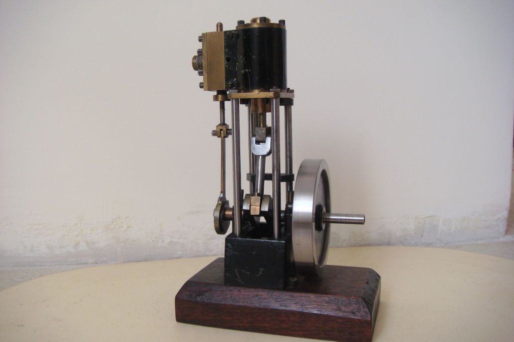
This engine is a two cylinder version of the single cylinder steam engine which my brother and I built in 1956/7 when we were kids in the South African town of Eshowe in what was then known as Zululand and is now called Kwazulu. The pic below shows this 50+ year old engine for which no design drawings were ever produced. It was built entirely from scrap metal using our father's old 3.5" screw cutting lathe.
DESIGN OVERVIEW
In November of 2011, when planning a two cylinder version of this engine, I decided to develope a design which allowed an option to build a single cylinder version. The two versions have many parts in common. Like the original, all parts are intended to be built from stock metal; no castings are required. Unlike the original engine which used the imperial dimensions and standards then current in South Africa, the new design uses the metric units and standards current in my adopted patria Italy.
The design was modelled in 3D and construction drawings were extracted from the models. The drawings for all the parts and assemblies for both versions occupy a total of thirteen A4 pages. I will attach each drawings to the post which deals with the parts on it.
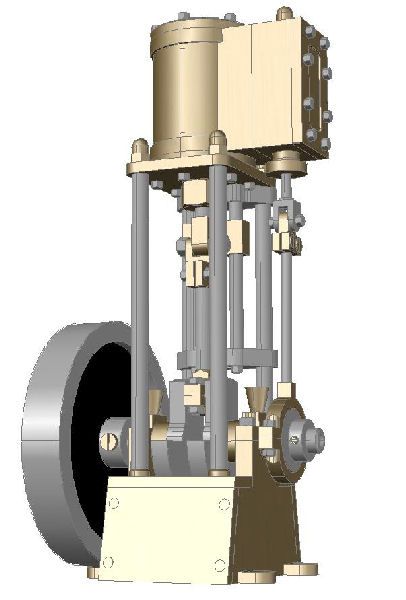
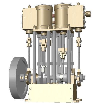
Below is a CAD generated image of the overall assembly for each of the versions. To give an idea of the size, the cylinder bores are 22 mm in diameter, the pistons have a 26 mm stroke, while the flywheel has a diameter of 72mm.
From here on I will refer only to the two cylinder version that I'm now building.
The design structures the engine into a number of assemblies. Here are the CAD images of their 3D models.
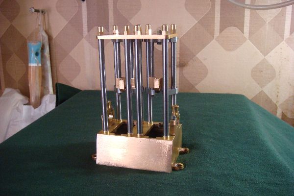
Base Assembly
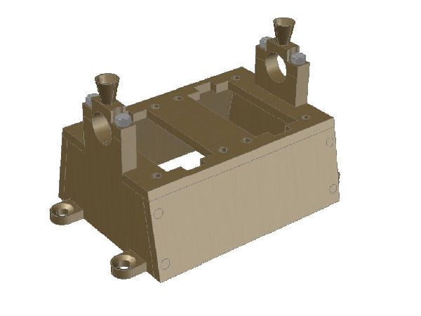
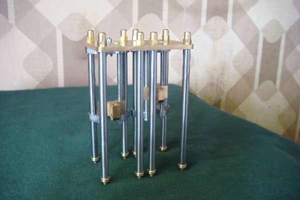
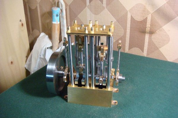
Vertical Structure Assembly
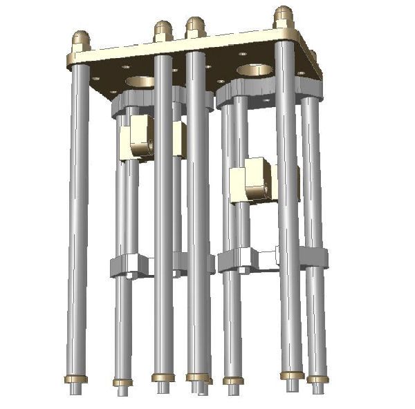
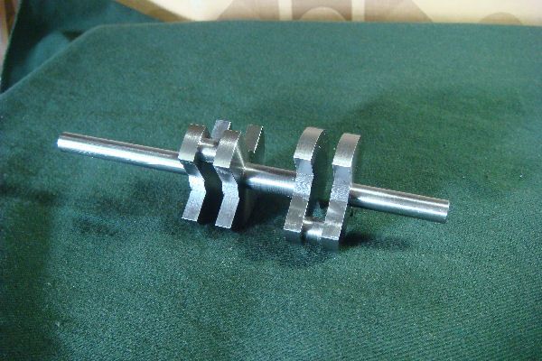
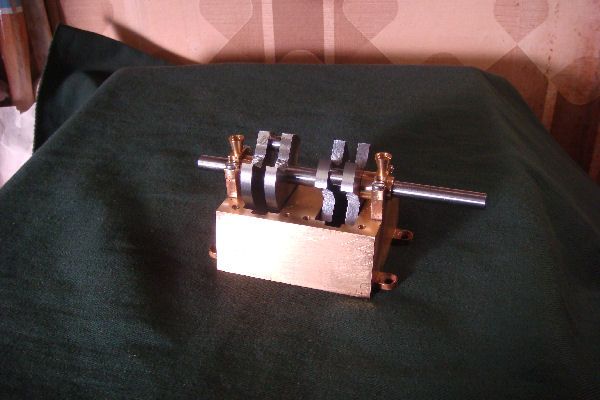
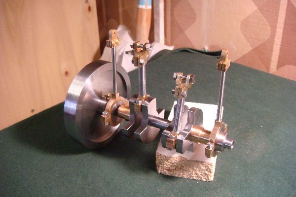
Shaft Assembly
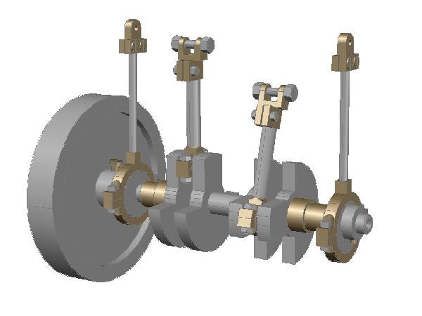
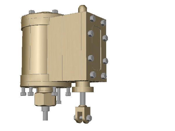
Cylinder Assembly
Two of these are required.
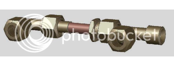
Inlet Piping Assembly
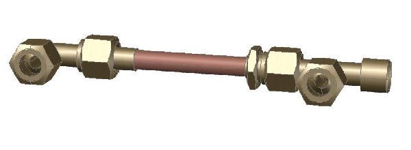
Exhaust Piping Assembly
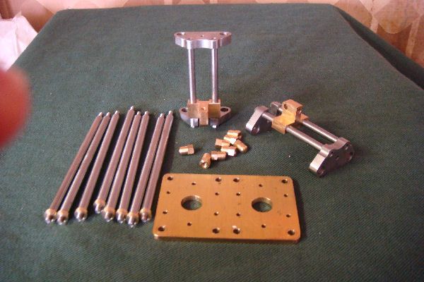
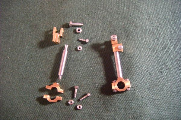
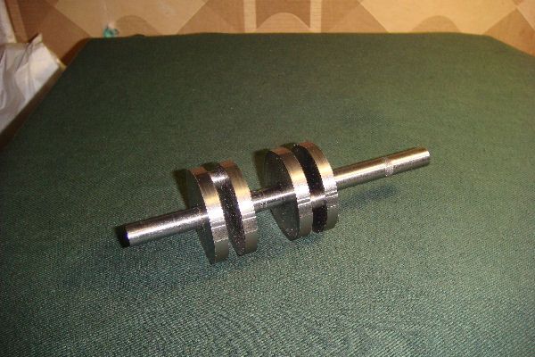
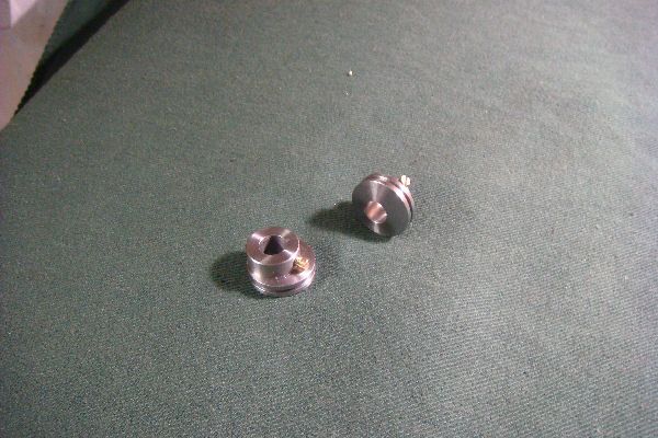
When work got interrupted last year I had completed building the Base Assembly and the Vertical Structure Assembly and all parts of the Shaft Assembly with the exception of the Crank Shaft itself, the Bearings, the Flywheel and the Eccentrics. I had done some initial work on preparing the chunks of steel destined to become the Crank Shaft and the Flywheel.
WHAT'S NEXT?
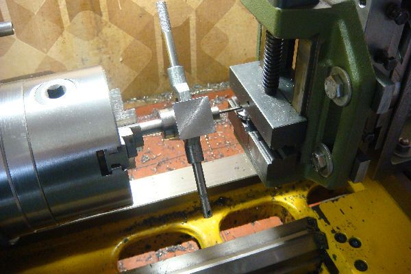
My next posts on this thread will report on these completed parts and assemblies; unfortunately I did not take many photos while doing this work.
Then I'll move on with more detailed reports as the work for completing the engine proceeds.
INTRODUCTION
I have resumed building the steam engine I had started when my encounter with HMEM caused me to embark on a fruitful interlude of tool building during which I learned much and for which I will always be grateful to HMEM and it's members.
This engine is a two cylinder version of the single cylinder steam engine which my brother and I built in 1956/7 when we were kids in the South African town of Eshowe in what was then known as Zululand and is now called Kwazulu. The pic below shows this 50+ year old engine for which no design drawings were ever produced. It was built entirely from scrap metal using our father's old 3.5" screw cutting lathe.
DESIGN OVERVIEW
In November of 2011, when planning a two cylinder version of this engine, I decided to develope a design which allowed an option to build a single cylinder version. The two versions have many parts in common. Like the original, all parts are intended to be built from stock metal; no castings are required. Unlike the original engine which used the imperial dimensions and standards then current in South Africa, the new design uses the metric units and standards current in my adopted patria Italy.
The design was modelled in 3D and construction drawings were extracted from the models. The drawings for all the parts and assemblies for both versions occupy a total of thirteen A4 pages. I will attach each drawings to the post which deals with the parts on it.
Below is a CAD generated image of the overall assembly for each of the versions. To give an idea of the size, the cylinder bores are 22 mm in diameter, the pistons have a 26 mm stroke, while the flywheel has a diameter of 72mm.
From here on I will refer only to the two cylinder version that I'm now building.
The design structures the engine into a number of assemblies. Here are the CAD images of their 3D models.
Base Assembly
Vertical Structure Assembly
Shaft Assembly
Cylinder Assembly
Two of these are required.
Inlet Piping Assembly
Exhaust Piping Assembly
When work got interrupted last year I had completed building the Base Assembly and the Vertical Structure Assembly and all parts of the Shaft Assembly with the exception of the Crank Shaft itself, the Bearings, the Flywheel and the Eccentrics. I had done some initial work on preparing the chunks of steel destined to become the Crank Shaft and the Flywheel.
WHAT'S NEXT?
My next posts on this thread will report on these completed parts and assemblies; unfortunately I did not take many photos while doing this work.
Then I'll move on with more detailed reports as the work for completing the engine proceeds.