A Smaller Steam Engine For A Smaller Boat

Home Model Engine Machinist Forum

Help Support Home Model Engine Machinist Forum:

This site may earn a commission from merchant affiliate links, including eBay, Amazon, and others.
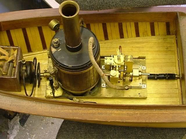
Back from the vacation and got a bit of time to work on the boat. What I came up with for a boiler feed pump is possibly the ugliest item I have made so far. I have to get better at planning ahead. My design on the fly attitude has served me well but more and more I see the need for plans. My lack of patience for drawing out designs is the biggest reason I haven't looked into CAD. I should since fusion 360 is free but that's a whole new skill for my already full brain. I have discovered if I learn something new I forget something old !

Anyway back to the modern art looking pump. I used 3/16 rubber balls for the check valves and cut the metal so that both ball seats are not buried in a bore of some kind. I did that because I haven't had great success with getting these types of check valves to seal well and I thought being able to inspect the seat and adjust it out in the open would help. I didn't take many pictures for these parts, I was just keeping my head down and cutting metal, kind of winding down from the trip overseas. I still need to fit a mounting bracket and plumb it in but quick test with no real load is promising. I will take an exploded view picture of the pump and post it to be more clear on the design
Pete
View attachment ImageUploadedByModel Engines1495805545.439394.jpg
View attachment ImageUploadedByModel Engines1495805557.174520.jpg
View attachment ImageUploadedByModel Engines1495805573.005599.jpg
View attachment ImageUploadedByModel Engines1495805588.811940.jpg
View attachment ImageUploadedByModel Engines1495805604.582578.jpg
 
Next is to build something to drive the pump. I wanted make a worm gear using a 5/16 - 16 tap. My plan was to hob a brass blank and just cut into it and reduce the diameter slowly until I like the reduction ratio. I didn't try calculating what I needed I just dove in. That didn't work out at all. Even at the smallest diameter I could thread the reduction was way too much, something new for the scrap bin. I went on a search to buy a set of gears. My setup requires the gear system to output at 90 degrees to the input shaft. I haven't tried to cut real gears yet let alone helical or bevel types. I didn't have any luck finding a source for what I wanted. Google suggested a ring and pinion set from an r/c truck ! I have a t-maxx and it goes thru parts like crazy so I looked through the spares I have and its ring and pinion are too big. A trip to the LHS and I came out with a nice 1/16 scale truck ring and pinion set. They look good and are made of something that carbide wont cut. I had to remove the center with a diamond grinding bit in my dremel. I started with a press fit sleeve to couple the pinion to the steam engine shaft. Then a couple of brackets to hold the ring gear and shaft. One adapter has been made to mount the ring to the shaft and I got to use the new toy my wife gave me. I have cheap Chinese scales on my mill and now they are connected to a blue tooth adapter and using TouchDRO. It works great and it allowed me to drill the three hole circle pattern in the adapter without using my rotary table. I highly recommend it ! It's been to long since geometry so I had to go to the internet to find a calculator to give me a correct radius for the circle. That was a long winded update wasn't it.
Pete
View attachment ImageUploadedByModel Engines1495805773.794820.jpg
View attachment ImageUploadedByModel Engines1495805786.462418.jpg
View attachment ImageUploadedByModel Engines1495805800.478814.jpg
View attachment ImageUploadedByModel Engines1495805824.691070.jpg
View attachment ImageUploadedByModel Engines1495805852.839586.jpg
View attachment ImageUploadedByModel Engines1495805880.807983.jpg
View attachment ImageUploadedByModel Engines1495805902.563221.jpg
View attachment ImageUploadedByModel Engines1495805926.447149.jpg
View attachment ImageUploadedByModel Engines1495806396.115034.jpg
View attachment ImageUploadedByModel Engines1495806432.234207.jpg
View attachment ImageUploadedByModel Engines1495806448.856979.jpg
View attachment ImageUploadedByModel Engines1495806463.487354.jpg
View attachment ImageUploadedByModel Engines1495806478.201358.jpg
View attachment ImageUploadedByModel Engines1495806494.625681.jpg
View attachment ImageUploadedByModel Engines1495806507.106309.jpg
View attachment ImageUploadedByModel Engines1495806520.006686.jpg
 
I'm still curious about using the tap to hob a worm gear. Have you been successful before with this technique?
 
Nope that was my first attempt, but a friend of mine has used that kind of setup to make worm gears. He uses a cut down bolt for the worm after using a matching tap. He has had guys use them for aiming telescopes so I guess they are pretty precise. I was looking for a 3:1 or so ratio and my taps won't work for that. Here is a link to someone pulling it off https://youtu.be/XIzlg_uObwQ
Pete
 
I have the other support made and the shaft in place for my ring gear. I will still have to drill a spot for a set screw to secure it to the shaft. I need to either make bushings for the shaft or source ball bearings. I have been thinking about swapping the crankshaft bushings for ball bearings just to allow the engine to spin easier, any thoughts ?
View attachment ImageUploadedByModel Engines1496287614.421974.jpg
View attachment ImageUploadedByModel Engines1496287577.137816.jpg
View attachment ImageUploadedByModel Engines1496287632.798696.jpg
View attachment ImageUploadedByModel Engines1496287644.110411.jpg
View attachment ImageUploadedByModel Engines1496287660.682053.jpg
View attachment ImageUploadedByModel Engines1496287679.319231.jpg
 
I have the other support made and the shaft in place for my ring gear. I will still have to drill a spot for a set screw to secure it to the shaft. I need to either make bushings for the shaft or source ball bearings. I have been thinking about swapping the crankshaft bushings for ball bearings just to allow the engine to spin easier, any thoughts ?
View attachment 89129
View attachment 89128
View attachment 89130
View attachment 89131
View attachment 89132
View attachment 89133

Pete,
I would use either brass or bronze bushings with an oil hole, I don't think it's worth the hassle of finding ball bearings as you are only going to use the boat intermitantly and you will have power in plenty with your engine.
With the shaft needing a grub screw, am I correct in thinking that it's a very hard metal that has to be tapped, if so why not machine a couple of annular rings on the shaft and glue it in with Loctite 603 and it will never move, as long as you are still able to take the shaft assembly out.
Remember that you don't have a lot of setting up time before it's impossible to move, the only way that I have found to loosen the Loctite is to heat the shaft with a blow lamp.

George.
 
Thanks for the idea George, but I shy away from more permanent ways of securing things together. I find that since I design on the go sometimes I have to back up and rework. Locktite would fight me on that. I did go ahead and bush the shaft with brass. I can always do ball bearings later.
I have the pump mounted and working ! I think the pictures will tell the story well enough. It took a lot of fiddling around to get it to fit and cycle correctly. I had to mount it with the piston opposite the drive because of space. I drilled a lot of holes in the flywheel for stroke adjustment so I can fine tune it to the rate of water used.
So that's about it for the big deal mechanical stuff so now It's all the little stuff. Soon it will be back to work on the hull.
Pete
View attachment ImageUploadedByModel Engines1496342478.600383.jpg
View attachment ImageUploadedByModel Engines1496342491.857457.jpg
View attachment ImageUploadedByModel Engines1496342510.741798.jpg
View attachment ImageUploadedByModel Engines1496342529.772924.jpg
View attachment ImageUploadedByModel Engines1496342540.837043.jpg
View attachment ImageUploadedByModel Engines1496342558.059646.jpg
View attachment ImageUploadedByModel Engines1496342573.495071.jpg
View attachment ImageUploadedByModel Engines1496342586.808598.jpg
View attachment ImageUploadedByModel Engines1496342671.164564.jpg
View attachment ImageUploadedByModel Engines1496342688.500746.jpg
 
Big day today ! I Have been working on plumbing and mounting all the power plant items in my little boat. This afternoon. I filled the boiler and oiler and lit the burner. In three minutes I had steam enough to run the engine and off it went ! Everything held together and seemed to work great. The noise in the video is mostly the Tmaxx driveshaft rattling. It gets a little better when I drag a finger on the prop so I hope a water load will help. If it stays loud I will look into making it quieter. The intake line on the pump is clamped in the video because it outruns the engine water consumption so that needs adjusting. I'm really pleased with the test. I won't do it again until I get the hull sealed and painted, oil gets all over so I don't want to soak the wood and then have trouble with paint sticking.
Pete
https://youtu.be/uo1wNHDhQdo
 
Pete,

I have to congratulate you on making a wonderful innovative steam plant, it runs a real treat and once that prop gets in the water, it will slow the engine right down and I am sure you will be hard pushed to hear any of the workings, just s-m-o-o-t-h runnings.

To protect everything inside (and outside) of the hull from water and oil penetration, I used to paint the inside and out with a product from the model aircraft lads called 'epoxycote'. It is a very thin epoxy, that once mixed up soaks into the wood and is self levelling so you end up with a rock hard impenetrable finish that is glass hard, The wood becomes almost like fibre glass but still retains all the beauty. I think it now also used for coating wooden flooring.

Absolutely superb!!

John
 
That is fantastic work Pete! I'm really enjoying this thread and amazed at your level of craftsmanship.

I'll bet you can't wait to get it on the water!

John W
Camp Verde, AZ
 
John - Thanks a lot ! I hope the water load will quiet things up. I tried to look up epoxycote and didn't find anything that was like you described, thin and penetrating. Also I plan on painting the boat because the woodwork was all superglued together so a clear or stain finish won't work due to the places the glue already sealed up. So would paint stick to the epoxy ?

John W - Thanks I appreciate that !!! I'm glad the thread is interesting and yes I am ready to run it !! Still got a ways to go. I gotta find a good sized captain to put in the hull to do the navigation.
 
Pete:

Slightly OT, but for a clear or stain finish over wood that been assembled with CA try a spit coat of clear shellac. At least I've always heard it referred to as a spit coat, you thin the regular mix of shellac at least 50-50 with denatured alcohol. This soaks into the wood and seals it so you can even stain over it and get consistent results.(Even on plywood - it virtually eliminates the typical tiger-striping.) I've assembled wooden models and wooden toys using CA then after sanding used a spit coat of shellac to seal the wood. The first time I tried on a model that had a couple of CA boo-boos I was amazed, with a clear finish I couldn't see any difference between the normal wood surface and the spots that had the CA boo-boos. After that particular model, I wasn't really too paranoid anymore about where the CA was going to run - as long as it stayed off my fingers.

Don
 
Pete,

Epoxicote is still available here in the UK, but a search for Epoxy Coat soon brought up a load of hits in the US, mainly from wood flooring specialists.

Maybe they will send you a sample as the ones I looked at were quoting for gallons of the stuff.

Hope this helps

John
 
Pete,
You can get finishing resin from hobby shops(rc aircraft) Z-Poxy by Pacer, it can also be thinned out further by using up to 10% methylated Spirits.

Cheers
Andrew

zpoxy.jpg
 
Pete,

Here are couple of pictures of my old Carvel planked hull which has been coated with epoxy. The decks on this one seem dull but that is because I had fine flatted it down ready for final polishing, it came out like a sheet of glass.

full_installation.jpg


The advantage of it is that it encapsulates the whole hull in like a very hard plastic coat, in fact, my steamer was always used to break the ice in the winter so that other boats could sail.

This picture shows the engine mounts in the bottom of the hull using sealed top hat inserts. Not only does it hold everything very rigid when tightened down, everything is totally sealed and just requires a quick wipe over to bring it back like new.

bare.jpg


Water and oil just doesn't affect it or get through it.


Sorry to hold you up on this build, just trying to assist.


John
 
This isnt holding me up at all this is great information. I really appreciate the feedback guys. I had no idea you could still stain even with superglue spills I will have to do some testing. I wanted the stained wood look for the boat but figured I was doomed to paint it. Z poxy is good stuff I glassed the hull of my sternwheeler with it. That would be a good option. That hull in the pictures is beautiful John !!!

Back to woodworking I added a bumper around the outside of the top of the boat and around the inside to give top some more going surface. I also added the rudder and its servo. There is now a mounting spot for the gas can also.
I cut out some paper to try to see what I want to the deck to look like what are you guys think of this? My wife is voting for no deck.
Pete

View attachment ImageUploadedByModel Engines1497054561.595490.jpg
View attachment ImageUploadedByModel Engines1497054572.730261.jpg
View attachment ImageUploadedByModel Engines1497054587.279373.jpg
View attachment ImageUploadedByModel Engines1497054602.522442.jpg
View attachment ImageUploadedByModel Engines1497054621.402108.jpg
 
Back
Top