A Smaller Steam Engine For A Smaller Boat

Home Model Engine Machinist Forum

Help Support Home Model Engine Machinist Forum:

This site may earn a commission from merchant affiliate links, including eBay, Amazon, and others.
Pete,

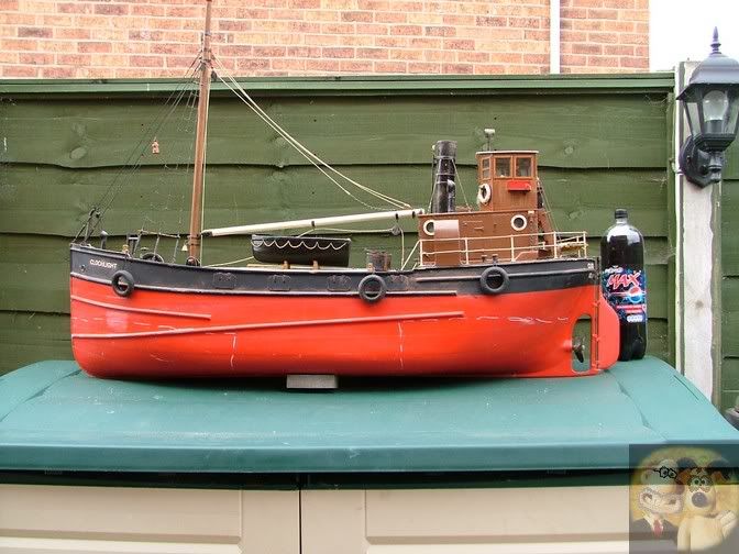
What Andrew said actually makes sense.

You might find that lots of ballast might be required to get the hull to its waterline (can't say designed waterline because you worked it out yourself), but even so, getting a good waterline is one of the first things you need to do, without it you could end up with a very unstable boat.

I made a 4ft long Clyde puffer, and even with a 100 amp hour battery in it, it was still too top heavy. I eventually put in internally sealed ballast tanks that allowed the boat to sink further, they contained another 5gallons of water weighing 50 pounds.

The chalk marks on the outside of the hull shows the rough position where the tanks were inside.

electric.jpg


You might have to resort to having a couple of large pop bottles full of water inside to achieve your waterline.


John
 
I appreciate the ideas, and yep it is what I should do. The engine will raise up some because it has been pointed out that this little engine will coat the belly with oil and water as it runs so a catch pan would be wise. It will mount to something so with all that it may be almost lined up. Silly thing is I have the universal setup in my head so for now I am just going to use the tmaxx shaft and then if I like the shaft and hate the plastic I will make a brass version. My next chunk of time is going to be in a prop. I got a quote for the prop and its going to be 40$ so I get to learn how to make the scrap under my bench into a propeller. I found this site - http://members.dodo.com.au/~sjbatche/making_propellers.htm I like the jig he made so that's what I will do.
I did float the hull again and threw lead car wheel weights in till I hit the shallowest I could go just submerging the prop under the surface and the stability got a lot better. I still have a inch or two to play with for waterline so even more lead can be tossed in. I might put a thick hunk of metal on the bottom for the keel too to protect the wood and that should help.
Pete
 
Pete,

Please try to use removable ballast, something like I suggested. Put boat into water and then add heavy ballast, reverse, for boat removal.

There is nothing worse than trying to lift a very heavy boat in and out of the water, just one slip on a muddy bank soon teaches what you need to do.
DAMHIK as the boat I showed above weighed well over 100 lbs when fully loaded with water in the ballast tanks, and who forgot to drain them before trying to lift it out of the water.
It was autumn as well and the water was freezing and very very wet.

John
 
Ok, does your boat flood those tanks from the water its sitting in ?
 
Yes, just open two taps and the tanks fill up from holes in the bottom of the hull once the main battery has been put in, remove battery, open taps and the hull automatically rises and empties it's tanks ready for lifting out of the water.

John
 
John - Ok I will remember that.

So work is going well on the prop I think. I am not looking for every last bit of thrust from the blades so researching the hydrodynamics of a blade are not on my list of things to do. This just has to putt around on a little pond and not fall apart. I drew out the shape I wanted and then cut out template for the metal. Tin snips cut the rough shape and then I sanded them to the lines traced out on the brass. To get the curve I used a deep well socket and a block of wood cut to the same shape. My vise smashed the two together and out came a curved blade. I wanted to remove a little pitch at the tips so I clamped up the root of the blade and then twisted the tip with another bit of wood that had a curved cut in it to hold the blade. Last was to file the root to conform to the hub which will be around a quarter inch round. Just for fun I superglued the blades together and spun the prop up in my cordless drill in a sink full of water. It seems to move the water pretty well. You can sort of see the spinning blades in the sink and the water pushing up the sides. I tried to spin it about what I expect the engine to turn but it's hard to know that.
Pete
View attachment ImageUploadedByModel Engines1490475082.354353.jpg
View attachment ImageUploadedByModel Engines1490475105.926848.jpg
View attachment ImageUploadedByModel Engines1490475116.244826.jpg
View attachment ImageUploadedByModel Engines1490475130.844989.jpg
View attachment ImageUploadedByModel Engines1490475144.858860.jpgView attachment ImageUploadedByModel Engines1490475158.831241.jpg
View attachment ImageUploadedByModel Engines1490475173.682395.jpg
View attachment ImageUploadedByModel Engines1490475222.897031.jpg
 
Only one problem Pete, I think you have the blades the wrong way around, the straight edges should be going forwards, other than that, looks to be a good prop.
BTW, it may mean you will have to make new blades to keep the prop turning in the same direction.

How do I know this?

I used to make props and refurbish and repair variable pitch props and modify blade shapes for certain people in the model boat fraternity. They are the only blade shapes that are the same front and back as they are designed to go fwds and back with the engine running in one direction only. All normal props have a leading and trailing edge.

Hub1.jpg


This is showing having to make a full new set of blade mountings and blades after one blade was lost in the water. It had to be done this way so that all the blades ran in the same space otherwise maybe one blade was trying to pull while the others were trying to push.
It is a shame I gave away all my prop jigs when I gave up model boating,
But this might help.

http://members.dodo.com.au/~sjbatche/making_propellers.htm

John
 
Thanks for the link for the prop jig. That will be what I use to set up mine. It's going to be out of wood just because I have plenty if it around and I'm only making one prop so burning it up will be ok 😀
 
I am so sorry that I sent you on a wild goose chase, it now looks like your prop is correct.

We used to call that type of straight back blades 'cleaver' type props, originally they were designed to help eradicate cavitation and aeration in props that were running close to or even piercing the surface of the water. It now seems, that since my time, this type of blade has become the normal sort of blade shape.

BTW, these are about the best props you can buy, lost wax cast in bronze or stainless, fully balanced and polished. These were only just starting when I gave up model steam boats, but even then, if you were willing to wait while they were made and pay the money, they were definitely worth waiting a few weeks for.

http://www.prop-shop.co.uk/products.php?cat=steam-scale

The ones I used to make and buy from Raboesch were straight fronted.

A sign of modern times I suppose.

John
 
Last edited:
John,
Not a goose chase at all. Its nice to have ya lookin out for me. It would be bad if you were silent and I made a bad prop. I didn't pick this shape for any other reason than I found a good picture of it and its a respected company that designed it. I'm sure theirs is better but this one should move the boat if the sink test was any indication. I wish I had seen the one you pointed before I made these blades, because its description sounds like its made for just my boat.
Pete
 
I worked on a jig for soldering up the prop. I used metal for the base but the rest is wood. I will see if it will hold up long enough to get this one prop in.
Metal work is finally making an appearance again on this machining web site. !! I turned a hub out of brass. The shaft will have an 8/32 threaded end so I drilled and tapped the hub to mount to the shaft. Next is trying to find a way to prove the blades are all exactly set the same.

While I had the blades loose I messed with their profile to more resemble the prop John showed me. It looked more like what would be expected on a boat like this. I might have gotten them closer to that look what do you think ?

Pete
View attachment ImageUploadedByModel Engines1490795621.718782.jpg
View attachment ImageUploadedByModel Engines1490795653.884785.jpg
View attachment ImageUploadedByModel Engines1490795675.935482.jpg
View attachment ImageUploadedByModel Engines1490795703.773315.jpg
View attachment ImageUploadedByModel Engines1490795722.039640.jpg
 
That looks very nice indeed Pete, as good as I ever made.

In fact, with steam, you could just use square or triangular flat plates because the engines run so slowly when loaded, and as long as the water gets pushed whatever way that is required, it will do. In fact, variable pitch props normally have flattish regular shaped blades, both fwds/bkwds with a tiny amount of curve.

John
 
Success ! The wood jig held up but just barely, the solder hardened up just in time before the wood turned to ash. If I was doing it again I would make the dowels out of metal. I cut the driveshaft and mounted the prop on it and then put it on my balancer and it didn't need any adjustments, it's plenty close enough especially for the rpm range it will run. A bit of polishing and it came out pretty good and it saved me $40+ !!
Pete
View attachment ImageUploadedByModel Engines1490906550.100309.jpg
View attachment ImageUploadedByModel Engines1490906564.774930.jpg
View attachment ImageUploadedByModel Engines1490906576.954350.jpg
View attachment ImageUploadedByModel Engines1490906590.210055.jpg
View attachment ImageUploadedByModel Engines1490906606.227799.jpg
View attachment ImageUploadedByModel Engines1490906615.761952.jpg
 
I mounted the prop shaft tube to the hull and then used a spare drive shaft from a tmaxx r/c truck to connect the prop shaft to the engine crank. I might fabricate a shaft out of brass some time later in but for now this is smooth and quiet and much stronger than it needs to be. The other benefit is it has a splined slip joint which allows for the engine to be disconnected really easily from the prop shaft. I have no idea how to make a joint like that. I can picture the male part of the joint but the female side is beyond me, anyone made something like that with manual machines ?

Now I need to get back to the boiler base and burner and finish them up. Once the boiler is done plumbing can begin. I am going to wait on the water pump stuff until I can run the engine off the boiler and get an idea of how much water it will use.
Pete
View attachment ImageUploadedByModel Engines1491008532.488132.jpg
View attachment ImageUploadedByModel Engines1491008552.037519.jpg
View attachment ImageUploadedByModel Engines1491008840.268950.jpg
View attachment ImageUploadedByModel Engines1491008856.491333.jpg
 
Disclaimer - I've never made one, so just my thoughts. If you can machine the male spline (which shouldn't be overly difficult considering you're making both halves) you could use it as a broach of sorts, especially if you make the internal part as a thin-ish insert of something soft like aluminium. If broaching a round hole into a spline is a bit much, you could always cast a rough pattern in aluminium so the broaching is more of a clean-up operation. For a small part like that you wouldn't need a furnace at all, just a blowtorch, and a lost foam pattern in dry sand would probably do the trick.

Otherwise, seeing as you're making both halves, why not simplify to a square drive for ease of broaching? There's load of info on broaching square holes with homemade tools online.
 
Pete,

The simpler you can make a coupling the better, what isn't there can't go wrong.

This is the type we used to use all the time. I used hollow Redthane tubing designed for making transmission belts, as it seemed to last forever, but I have also used thick walled silicone tubing if I required a rather larger offset similar to yours. Up to 3" long presents no problems. I have also used solid rubber where I made cups for the rubber to fit into, then pinned it through to hold things in place, but modern day adhesives should work well.

This article shows exactly what I mean. From the same place I showed you the propeller jig.

http://stevesmodelshipshed.com/dir/?page_id=442


John

PS. Don't forget to fit a stop collar on the inboard end of your propshaft, as when you put the engine in reverse it will try to pull the shaft out of it's tube as you have a sliding coupling.
 
Last edited:
Thanks John that coupling is a simple setup. Still not shire where I will end up with the shaft. I plan on putting a sleeve on the dry side of the shaft with a bit of delrin to give a slippery surface to bear on to stop any fire and aft movement.

Got a bit of time this weekend to work on the boat. I worked on a base to the boiler. I made a holder for the jet I scavenged from a backpack stove. I am also using the burner and gas valve from the same. With a bit of fiddling with the air holes I was able to get a nice flame that burns fine in the enclosed base. Looks like I don't need secondary air to keep it lit. I was able to raise 1 bar of pressure in 4.5 min from a cold uninsulated boiler. It keeps climbing fast but I didn't go much further since I don't have any safety valves made yet.

I also started work on mounting the engine and boiler in the hull. I bent up a drip pan to catch the drippings from the equipment. I didn't want to put holes in the pan so the support for the machinery will come from outside the pan. I took an idea from the cheap Chinese bookshelf I put together recently. I don't have any luck threading wood for these tiny fasteners. I took some 3/16 brass rod and drilled it for the 4-40 screws I want to use to hold the engine mount to the hull. I drilled the wood mount in the boat for the brass "nut" and then drilled down to match up to the threaded hole. Now the brass nut will have a hard time being pulled out of the wood it's in.
Hopefully the pictures will explain it better than my writing skills.

Pete
View attachment ImageUploadedByModel Engines1491236340.233623.jpg
View attachment ImageUploadedByModel Engines1491236359.368577.jpg
View attachment ImageUploadedByModel Engines1491236372.287087.jpg
View attachment ImageUploadedByModel Engines1491236387.653619.jpg
View attachment ImageUploadedByModel Engines1491236528.408235.jpg
View attachment ImageUploadedByModel Engines1491236542.101991.jpg
View attachment ImageUploadedByModel Engines1491236557.486105.jpg
View attachment ImageUploadedByModel Engines1491236573.402188.jpg
View attachment ImageUploadedByModel Engines1491236589.717919.jpg
View attachment ImageUploadedByModel Engines1491236605.888620.jpg
View attachment ImageUploadedByModel Engines1491236620.180516.jpg
View attachment ImageUploadedByModel Engines1491236632.377312.jpg
View attachment ImageUploadedByModel Engines1491236650.819111.jpg
View attachment ImageUploadedByModel Engines1491236662.524566.jpg
 
Back
Top