This week has been clean-up week for me, I have a pile of little jobs on my bench that I need to get out of the way. This is not exactly an engine related project......yet.
I had thought about adding to Dean's excellent post on gear cutting, but I decided to start a new thread, as this is just a little bit different machine and method.
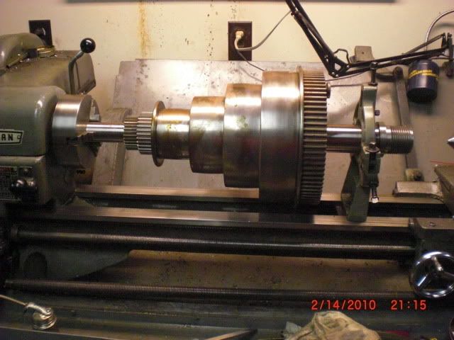
I have a lathe in my shop that I have been working on that had some gear problems. One of the back gears had shed a few teeth, and the tumbler gears had some problems as well ( one missing, one completely worn out). This lathe was built in the late 1800's, so finding parts has been a little more than difficult.
The first problem to get taken care of was turning the tumbler gear shafts to true them up again. Not at all concerned with size, I'll make the gear bores to suit, but the shafts were not going to let themselves be removed, so.......
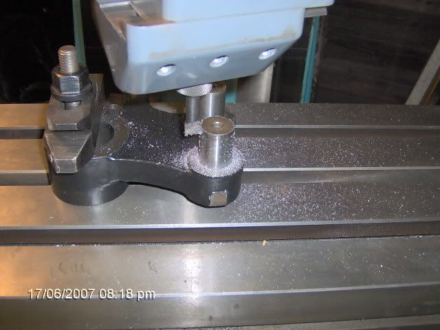
we turn 'em with the boring head.
Now I need gears. The blanks were turned up and an mandrel made in the same manner as Dean had done. The gears I am working on are a bit bigger and I'm using my horizontal mill. Getting the dividing head set up for this takes a little bit of time, and the following is just the manner in which I set up, not by the book...maybe not even correct according to some; but it works for me.
I had to transfer the mandrel from the lathe to the dividing head, so it needs to be trued up in the dividing head. I indicated it on center close to the chuck, and at the tailstock end by using the adjustment screws in the chuck and tapping the end around with a brass hammer. Once it was running true, I aligned the dividing head with the table.

By setting the indicator this way, I can crank the knee up and down to locate the highest point on the mandrel, which is center, and keep track of the reading. Then by moving to the other end of the mandrel, and again finding the high point, I can bump the dividing head around until I get the same reading on both ends.
Now that I'm aligned with the table, I need to get the vertical alignment.

Same method, just running the saddle in and out to locate my high points. The alignment done, the tailstock is slid into position and clamped.
This gear is 24 teeth, and this being a 40:1 dividing head, the plate needs to be fitted for the correct spacing. 40/n gets you the numbers you need, so 40/24 = 1 2/3. That's one full turn and 2/3 of another. A hole circle divisible by three is the one to use, so I can use 10 holes in a 15 hole plate, 12 holes in a 18 hole plate, 14 holes in a 21, etc. I decided on an 18 hole circle (third row in from the outer edge) to keep the crank handle as long as possible for easier turning.

Then by setting the sector arms so there are 13 holes between them, I don't have to count off my 12 holes for the 2/3 turn.
I'm going to "gash" the teeth first to take some of the load off of the gear cutter, so on goes a 3/32 slitting saw.

Just a tip here, don't attempt to tighten the arbor nut at this point, very easy to bend an arbor by doing this.

With the arbor support in place and clamped, now the arbor nut can be tightened.
Finding the center of the gear blank on a horizontal can be a problem, the cutter is too small to reach down the side of the gear blank, and there isn't any room to get to the mandrel. Got some of those cheapa$$ 1-2-3 blocks? Here's a use for them.

With those set up against the gear blank, and knowing the gear blank diameter and the saw thickness, a little simple math will tell you the distance the side of the cutter should be from the 1-2-3 block. That figure, a depth micrometer, and three hands will tell you where you actually are.

The correction to get you on center is easily done by dialing it off on the cross slide handwheel.
I like to set the depth of cut at about .002" and go around once to check my setup for correct spacing. If everything is as planned, I'll wind up with 24 teeth gashed in,

like so.
Comments and criticisms are welcome.
Thanks for looking.
Kevin
I had thought about adding to Dean's excellent post on gear cutting, but I decided to start a new thread, as this is just a little bit different machine and method.
I have a lathe in my shop that I have been working on that had some gear problems. One of the back gears had shed a few teeth, and the tumbler gears had some problems as well ( one missing, one completely worn out). This lathe was built in the late 1800's, so finding parts has been a little more than difficult.
The first problem to get taken care of was turning the tumbler gear shafts to true them up again. Not at all concerned with size, I'll make the gear bores to suit, but the shafts were not going to let themselves be removed, so.......
we turn 'em with the boring head.
Now I need gears. The blanks were turned up and an mandrel made in the same manner as Dean had done. The gears I am working on are a bit bigger and I'm using my horizontal mill. Getting the dividing head set up for this takes a little bit of time, and the following is just the manner in which I set up, not by the book...maybe not even correct according to some; but it works for me.
I had to transfer the mandrel from the lathe to the dividing head, so it needs to be trued up in the dividing head. I indicated it on center close to the chuck, and at the tailstock end by using the adjustment screws in the chuck and tapping the end around with a brass hammer. Once it was running true, I aligned the dividing head with the table.
By setting the indicator this way, I can crank the knee up and down to locate the highest point on the mandrel, which is center, and keep track of the reading. Then by moving to the other end of the mandrel, and again finding the high point, I can bump the dividing head around until I get the same reading on both ends.
Now that I'm aligned with the table, I need to get the vertical alignment.
Same method, just running the saddle in and out to locate my high points. The alignment done, the tailstock is slid into position and clamped.
This gear is 24 teeth, and this being a 40:1 dividing head, the plate needs to be fitted for the correct spacing. 40/n gets you the numbers you need, so 40/24 = 1 2/3. That's one full turn and 2/3 of another. A hole circle divisible by three is the one to use, so I can use 10 holes in a 15 hole plate, 12 holes in a 18 hole plate, 14 holes in a 21, etc. I decided on an 18 hole circle (third row in from the outer edge) to keep the crank handle as long as possible for easier turning.
Then by setting the sector arms so there are 13 holes between them, I don't have to count off my 12 holes for the 2/3 turn.
I'm going to "gash" the teeth first to take some of the load off of the gear cutter, so on goes a 3/32 slitting saw.
Just a tip here, don't attempt to tighten the arbor nut at this point, very easy to bend an arbor by doing this.
With the arbor support in place and clamped, now the arbor nut can be tightened.
Finding the center of the gear blank on a horizontal can be a problem, the cutter is too small to reach down the side of the gear blank, and there isn't any room to get to the mandrel. Got some of those cheapa$$ 1-2-3 blocks? Here's a use for them.
With those set up against the gear blank, and knowing the gear blank diameter and the saw thickness, a little simple math will tell you the distance the side of the cutter should be from the 1-2-3 block. That figure, a depth micrometer, and three hands will tell you where you actually are.
The correction to get you on center is easily done by dialing it off on the cross slide handwheel.
I like to set the depth of cut at about .002" and go around once to check my setup for correct spacing. If everything is as planned, I'll wind up with 24 teeth gashed in,
like so.
Comments and criticisms are welcome.
Thanks for looking.
Kevin