1st Engine - An HMEM EZ-Engine Build

Home Model Engine Machinist Forum

Help Support Home Model Engine Machinist Forum:

This site may earn a commission from merchant affiliate links, including eBay, Amazon, and others.

hakuna

Member
Joined
May 16, 2010
Messages
12
Reaction score
0
Hi All,

This is my first post!

First let me say thanks to black85vette for putting together these plans! I needed a simple project and found these. I didn't realize it was such a recent creation (just a year ago). I wonder how many of these are out there now?

I'm learning to use my first metal lathe (A Sherline) with a milling attachment. I have it hooked up for CNC (I teach computer technology and plan to teach some CAM to high school students and to use it for our robotics program), but for this project I'm just jogging the wheels with the computer. Essentially just using the computer as a DRO machine.

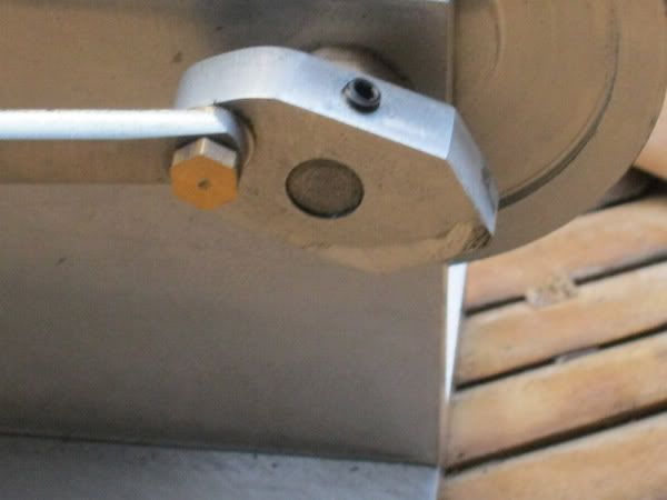
Here's some of my first pics. I'm teaching myself how to do lathe work, using the Internet. The basic machining skills are coming along well...I'm learning from all my mistakes!

Any suggestions and/or comments are welcome.

Gary
 
Here are the basic components I have so far. The Cylinder and Valve Block I have done. I faced the mating surface but didn't bother with the others. The Piston is done. The Valve is done.....WRONG! But I think it will work. I think the last bit is too small...0.125 instead of 0.250 in width. But if the 0.750 sections at 0.125 diameter are there and the section separating them is 0.250 I think it will work. If not I'll make a new one.

The salvage block of aluminum I'll use for the frame. I can only make a 2 1/4" dia flywheel with this frame, but I think I can make it almost 1/2" thick, so that should do for mass.

The cylinder with a hole is a tapping guide I made for my 4-40 tap.


EZ-Engine01.jpg
 
I used my milling attachment to mill the flat on the valve...I did the piston with a file. I wish I had a reamer for the cylinder and valve holes...I just used a drill. Seems smooth enough though.


EZ-Engine02.jpg


EZ-Engine03.jpg
 
I managed to wreck my first attempt at the Engine frame. Well, not wreck, but I have a few of those salvaged blocks so I'll try again. What happened was that the air pass-through hole is 0.125. The other four holes are for tapping 4-40. Guess what? I drilled them all 0.125!!! I could "fix" it, but I'll just use the bad piece for the crank.

Thanks for looking!
Gary
 
Gary,

Welcome to our forum. wEc1

Best Regards
Bob
 
Hi Gary, and welcome. Ain't it a B***H making simple mistakes :big: It's OK though, that is how we all learn. Would it be at all possible for you to go up one size for your tapped holes? ei: 5-40 or perhaps 6-32? If you have enough material around the holes that is. It would be a shame to scrape a good piece but good practice to make another. six of one, half-a-dozen of the other as they say. So far you are doing quite well.

BC1
Jim
 
Welcome to the forum. You have already found one of the issues you learn to deal with and that is minor mistakes. When faced with this just step back and see if you can figure a way to adapt or improvise a solution. As Bearcat said, you can use a larger tap / screw.

Another possible solution is to just turn the vertical plate over and use the other side. Fill the holes with JB Weld and paint over them. Nobody will ever know.

Problem solving can actually be an enjoyable exercise.

Hope you have fun with the build. Keep the pictures coming.
 
Hi Guys,

Thanks for the comments! When I drilled the holes too large, the first thing I did was look at my tapping guide hoping I could just put in bigger screws. 6-32 would work fine I think. I have about 8 of those 1/2 salvage plates though, so I'll just do it right. I need to use one to make my crankshaft flywheel anyhow. WHICH brings me to my next question. I don't have a metal bandsaw so I want to use the mill to cut out the crank. I drew up this plan for it in MasterCAM... it's about an inch across. The stock is 1/2" aluminum. I have a mill vise, but no simple hold downs (I need to make some). So I was thinking a simple way to do this would be as follows:

1) drill out the center at 0.125 (the final diameter will be 0.25")
2) screw the stock down to a sacrificial plate through this hole (or maybe some faced hardwood?)
3) Mill it CNC using depth cuts and WD-40 as coolant between depths.

Does this sound logical? Use a 1/4 end mill? (Wow I'm a newbie.)

Thanks!
Gary


crankfly.jpg
 
Ok, THANKS guys. I went back into the shop this evening and looked at the frame. It started to seem like a lot more work to remake it from scratch than just to tap out the mistaken holes to 6-32 and see if there was enough "meat" on the valve block. I checked and sure enough it appears to be good. So I tapped it and all is well!!! I can see this forum is going to be a big help.

I took some pictures of the frame. I mounted the cylinder and LOOK, my air hole lines up. LOL. Doesn't seem like I should be all excited, but I was....

Thanks and I definitely need to know what you guys think about my last post #8. I'm not sure if cutting something out with a 1/4" end mill in aluminum is the way to go on a mini-mini-CNC-mill. I've only done wood and plastics.

Thanks again,
Gary

P.S. The "sixth" hole to the bottom right of the top picture was in the original salvage piece of aluminum... it's not a part of the project.


EZ-Engine04.jpg


EZ-Engine05.jpg


EZ-Engine06.jpg
 
Dear Gary
I'm new at this also and made one of these engines as my first steam engine recently.
I just made the crank from a scrap of ally bar. I cut the ends to a diamond with a 6mm end mill and hand filed one end a bit round. The central hole and the pivot hole were drilled on the mill. I drilled a 2.5mm hole and tapped it to 3mm for a grub screw that I had bought in bulk from these guys.
http://cgi.ebay.com.au/3-5mm-Grub-S...Radio_Controlled_Vehicles&hash=item58819b2072
or here
http://cgi.ebay.com.au/3-5mm-Grub-S...Radio_Controlled_Vehicles&hash=item439f20908e
for virtually nothing.
I'm sure similar would be available world wide.
I don't think the shape of the crank is at all important but the distance from the centre is.
see here.
crank.jpg
 
Thanks for that link Doc,I just bought some of those screws.

Regards,Ian (seagar)
 
Thanks for the help DOC123. My first attempt at CNC cutting the crank failed miserably. I made the depth cuts too deep and pushed the piece off it's clamping. Oh well...I'll try again soon.

Ok, next problem: I made a bushing for the crankshaft, my first one and it came out really nice I think. It fits the frame with just a small but firm press of the thumb. Yay! BUT the catch is that I put it into the frame and looked at it and the HOLE in the frame isn't perpendicular. ARRGGH. The frame must have been cocked slightly in the vise when I held it to drill the hole. Oh well, I guess it was in the cards all along that I make a new frame.

EZ-Engine07.jpg


EZ-Engine08.jpg


EZ-Engine09.jpg
 
I found some nice brass stock this week. I got about 6 inches of 2.5" brass round and about 7 inches of 1.5" brass round. $4 a pound. I chucked up the huge piece (huge for a Sherline) of brass round, faced it and turned it down to 2.2 inches (max diameter for my frame). I cut the piece off in a metal bandsaw turned it around and then faced that rough side on the lathe. You can see that part in the picture. I may need to continue cutting a bit but I want max thickness for the flywheel.


EZ-Engine10.jpg


EZ-Engine11.jpg


EZ-Engine12.jpg
 
Nice shiny flywheel. ;D
Mine was just a bit of ally. Doesn't look anywhere near as good.
 
Hi all..this is my first post.
There is a wealth of info and experience on this thread and I'm glad I'm not the only one who has 'oh b@*%er' moments.

with regards the engine frame: you could make a new centre drilled only bushing that is a press fit and then drill/ream the whole frame and bushing straight as one . would save making a new frame.

Iain
 
Back
Top