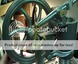
1/4 Scale Rider-Ericsson Pumping Engine

Home Model Engine Machinist Forum

Help Support Home Model Engine Machinist Forum:

This site may earn a commission from merchant affiliate links, including eBay, Amazon, and others.
Bill

Great job on your Rider-Ericcson; I'll bet it is going to run real nice. My good friend built one last winter and it runs like a Swiss watch and takes very little heat to operate.

One interesting thing he has had happen on the Teflon power piston packing was after running a while it would shrink and leave a considerable gap. I think eventually he just cut a small piece to fill the gap; because if he replaced the whole thing it would just do it again.

I told him that it was the cheap Chinese packing that he had purchased from the Ace Hardware store.

Thanks for the update,

Dave
 
Love the idea of "parting off" using a slitting saw; stored away for future use ;)

Jan
 
Today I finished up the crank disc before jumping into some of the shoulder bolts. Now I can spin the flywheel all I want without the crankshaft wanting to slip axially in the bearings. I started with a piece of rectangular aluminum and flycut it to the required thickness, then drilling and boring the .500" hole for the crankshaft and the tapped hole for the crankpin. The RT was used again with a ball end mill to form the relief on the back side (opposite the crankpin) as shown in photo 1. This was followed with a straight end mill to finish the outer radii of both the large and small ends (photos 2 & 3). Though it doesn't show well, I had made a .500" round stud with 10-32 threads to screw into the crankpin location to hold the small end on the RT with the lathe chuck, securing the back side with a 10-32 nut. I was still cautious of it letting go and spinning during the milling of the small radius, so took small cuts and held the big end with my fingers. Fortunately it held well. Once the round work was done it was a matter of straight cutting the edges tangent to both the large and small radii. Photo 4 shows this set-up in the vise and as it turned out a 1/4" square toolbit and a #60 drill under the brass stud gave a close enough angle so that a little filing and sanding could blend everything together seamlessly.


IMG_1127.JPG


IMG_1128.JPG


IMG_1129.JPG


IMG_1130.JPG
 
After drilling for the 8-32 set screw i mounted the crankdisk on the lathe on a 1/2" dowel pin and cleaned up the recessed side a bit more, then some final sanding on the surface plate and it was ready to go.


IMG_1132.JPG


IMG_1131.JPG
 
Hi Bill,
Great work as usual. I have always like the looks of this engine. Just not enough time. :big:
gbritnell
 
George, thanks for checking in.

Dave, the packing I got from McMaster was 1/8" square. I was hoping it would compact enough to fit in the gap but no such luck. Yesterday I got some 3/32 round from the local hardware and sure enough, it comes from China. It fits the gap perfectly and seals against the cylinder without too much drag, but i can see the issue you noted. For now i am going to see if the 1/16" gap will be ok, if not I'll probably do the same thing and just fill the crack as needed. I'll see how it wears first. Thank for the heads up though.

Jan, I have used the same technique for making fins in cylinders too. On the smaller Sherline machines I feel like it gives me more control and a more rigid set-up compared to using a parting tool on the lathe.

Bill
 
Starting to come together in places now...here is a short video of the linkages working off of the crankdisk...

 
Awesome stuff Bill!!!
Looks like it is going to be a very smooth runner very soon!

Andrew
 
A little progress since the last post...had to stop my the local metals supermarket and procure 2 sizes of brass, one for the power piston center and one for the pump body. The three pictures below show the roughing out of the piston centerpiece. A bolster for the links to attach to will be soldered into the cross hole shown. Also a bronze bushing fits into the threaded end to guide the displacer rod which workd up and down through the center of this piece.


RE Build 060.jpg


RE Build 061.jpg


RE Build 062.jpg
 
Meanwhile as time allowed ofer the last day or so a couple of other smaller pieces were made. First the connecting pin that joins the two 3/16 square actuators that (make a "U" shape above the beam). This will ultimately mate with another brass rod end that extends from the top of the displacer rod. Theother piece (actually two pieces not yet parted) are the steel pieced that will solder onto the 3/16" square arms and attach them to the connecting pin as shown in the last photo. Once I split this into two parts they will be milled to length and a 3/16" notch put in the free end of each to fit to the square actuator rod.

RE Build 063.jpg


RE Build 064.jpg
 
Despits havig to cut that pesky grass this weekend, I got some good shop time in as well.First up I wanted to make the two parts that form the displacer actuator "bow." Once each piece of 3/16" square stock was bent to 90 degrees (photo 1). The plans call for 1.32" from the inside of the vertical portion to the cut off end of the bend. To get this I cut a scrap piece of brass to that dimension and the used it to set the slitting saw height to make this cut in each of the two bow halves (photos 2 & 3). The end pieces were finished and notched for silver soldering to these ends as shown in photo 4'

IMG_1142.JPG


IMG_1139.JPG


IMG_1141.JPG


IMG_1143.JPG
 
After soldering and cleaning up the end pieces, the sharp corners were radiused with a abll end mill and attached to the center connecting part to form the whole bow. I wanted to check the fit before making and soldering the lowed rod ends and the bow is wider than the actuator arm casting by about .160" ...hmmmm. ???. I rechecked every dimension and everything was spot on to the plans. At that point I added up everything on the plans and came up with 3.960" between the bow legs while the finished width of the actuator casting is 3.800". I think rather than modifying the bos legs I will just add a spacer to each side of the actuator armto fill the gap of .080" per side. Anyone planning to build this model should make a note to change the 1.32" dimension noted in the previous post to 1.24" +/-'


IMG_1144.JPG


IMG_1146.JPG
 
Leaving the displacer bow for a while, I also wanted to get the power piston finished and installed to check out all the linkages. The cross piece was made and loctited in and the link arms attached (photo 1). then the center piece was installed into the piston casting as shown in photo 2. Finally, the last two photos show the power piston assembly installed into the cylinder and the other end of the links attached to the beam.

IMG_1147.JPG


IMG_1148.JPG


IMG_1149.JPG


IMG_1150.JPG
 
Bill

As usual beautiful workmanship. I guess not much left to get it finished.

Vince
 
Thanks Vince, mainly whats left is the hot cap, pump, and plumbing. Its getting close now and this weekends progress helped a lot. Once everyting is made and a test run is made it will be disassembled, and painted.

Bill
 
That's a very interesting looking engine, watching the links when it is running will be a treat.

Jan
 
Thanks Jan, I do think that is what attracts many to this engine or similar ones...as well as the fact that it performs work too, in this case pumping water. I look forward to getting to the point where I can post a video of it running...hopefully not too much longer.

Bill
 
Wow!!!! :bow:
More excellent craftsmanship Bill!

All the linkages, the bow and the fit looks amazing.
Eagerly awaiting it's first test run!!

Andrew
 
It sure is coming along nicely Bill. As stated your craftsmanship is first rate. This will certainly be another fine addition to your collection.
gbritnell
 
Andrew and George....thanks so much for the comments and support. As luck would have it I have to be gone from Wed. until Sun this week so progress may be slowed a bit until my return. Ah...to be retired and only have to commute to a back yard shop each day!! :big:

Bill
 

Latest posts

Back
Top