1/4 Scale Rider-Ericsson Pumping Engine

Home Model Engine Machinist Forum

Help Support Home Model Engine Machinist Forum:

This site may earn a commission from merchant affiliate links, including eBay, Amazon, and others.
One of the last more worrysome tasks on the cylinder casting was to bore the top and bottom to accept the cylinder sleeve thus forming the water jacket around the cylinder. This required two different diameters 2.20" at the top and 2.16" at a bottom distance of 4.62" from the top surface of the casting. As before, I left the cylinder casting mounted to the base although this time with the added support of the flywheel bracket being attached. The very bottom of the cylinder casting had been bored previously while doing the lathe work (earlier post) so this provided a reference to center on with the coax indicator (photo 1). Once this was done the top bore of 2.20" was easy enough, visible and measurable, but to reach far enough down to make the lower bore of 2.16" I had to use a longer boring bar which was below the top of the cylinder even with the knee in the full lowered position (photo 2). I used a steel rule to measure from the tip of the boring bar back up to the top of the casting and then subtracted that from the 4.62" depth needed. A little error here shouldn't be that much of an issue. A telescoping gage was used on both the top and bottom bores until the diameters were just an interference fit with the respective diameters on the cylinder sleeve (photos 3 & 4).

RE Build 040.jpg


RE Build 041.jpg


RE Build 042.jpg


RE Build 043.jpg
 
Now for the moment of truth...would it fit properly? Fortunately it did as shown in the below photo. Its not fully pressed in at that point. I am electing to use JB Weld to secure and seal these two locations of the liner to the casting. Loctite would be a little neater but I'm not sure it would seal as well. If all else fails I stil have access to both the top and bottom of the liner sleeve if additional sealing is necessary. Glad that task is done now!!


RE Build 044.jpg
 
Great progress Bill!!!

I seem to have missed the ones from the weekend, so i had a bit
of catching up to do!

Andrew
 
Boring a hole that deep must have been exciting, not being able to see the cut in progress. Did you get any vibration from the boring bar? I can see for the first time how much easier it is to centralise the workpiece on the mill table rather than using a 4 jaw or faceplate on the lathe.
 
No worries Andrew, progress has been steady but slow so not much catching up to do.

ProdEng, It wasn't bad actually, had the mill in low gear, and the aluminum casting machines well. Still took shallow cuts but there wasn't that much to remove from the bottom end. Having the whole thing mounted to the base and the extra support of the flywheel bracket helps also.

Bill
 
Well since today seemed to be cylinder day, I finished up by drilling the outlet port for the water jacket on the back side of the cylinder casting and the inlet port and pump mounting holes on the end of the casting. The outlet will be tapped 1/4-40 for model pipe and as soon as I can get that done at home tonight and clean the water jacket area of chips and such I will mount the liner into the casting let it cure before testing for leaks.

RE Build 045.jpg


RE Build 046.jpg
 
The power piston is small enough to work on at home on the Sherline lathe. Beginning with the raw casting (photo 1) the OD was turned to within .010" of the bore diameter (photo 2). Even taking small cuts of .010 to .020 built up some heat in the casting. Before working on the last .010" i let it cool back to normal temp. since even 40-50 degrees could result in a tenth or two difference due to expansion. The last few tenths were "dusted" off with a small piece of scotchbrite (photo 3) with repeated checks in the cylinder liner until the piston would just slip it on it own weight and be damped by closing off the open end of the liner.


IMG_1046.JPG


IMG_1055.JPG


IMG_1056.JPG
 
Once i was happy with the OD fit in the liner the end of the piston was drilled and bored to .500" (photo 1). The excess casting material was faced off the bottom end (photo 2). This did reveal a few small voids in the casting which shouldn't affect performance but I will fill them in with some JB weld all the same. Finally the bore was enlarged for the retaining nut which will hold the piston rod in place (photo 3). Tomorrow evening I will add the oil grooves, part the piston off and begin work on some of the inside contours. Thanks for checking in on today's progress.


IMG_1057.JPG


IMG_1058.JPG


IMG_1061.JPG
 
Hi Bill,

I see you are using a tangential tool in the second pic.
How do you find it works for you?
From the pics it looks like it is doing a fantastic job!

I am quite interested in making one for the Myford and if i can pull that off, one for the South bend too.

Great work again!!!

Andrew
 
Andrew, I have had the "diamond" toolholder for several years now and like it very much. It isn't a cure all by any means but like any tool it has its place. It is convenient to buy a square HSS blank toolbit (1/8" square in this case), chop it in half and sharpen both ends of each half...4 cutting edges for a small price. As with any cutting tool, sharpening is critical, but with the supplied fixture for sharpening (which I'm sure you can make just as well), that is pretty straightforward in this case as the angles are all built into the sharpening fixture. For me it isn't necessarily my #1 go to tool for facing or turning, but it does get used often. The reason I used it in the above case is that the piston is too large to clear the cross-slide and the diamond toolholder offered greater extension to the left of the cross-slide so I could machine firther back towards the chuck.

Bill
 
Ii got a start on the flywheel today. I first chucked on the largest hun of the casting and got the flywheel running as true as possible. Then drilled an undersized through hole (photo 1). Boring it for a light press fit on a .500 dowel pin came next (photo 2), followed by support from the live center in order to face one side of the outer rim to width. Once the outer rim was faced the hub was also faced to a slightly wider width (photo 3). Although not shown, the outer diameter of the rim was machined next. The dowel pin was pressed into the machined side so that it can be chucjed on to machine the opposite side of the flywheel tomorrow.


IMG_1062.JPG


IMG_1063.JPG


IMG_1064.JPG
 
Couldn't help but see how the flywheel looked in the whole scheme of things Photo 1) even though the spokes will be reversed in the end. The last picture is of the outlet connection into the water jacket with an elbow attachedjust to make sure it wil clear the flywheell and stack.


IMG_1066.JPG


IMG_1067.JPG
 
Starting to come together now Bill!!! ;D

Looks like the water jacker connector just clears the flywheel.

Andrew
 
Not quite as close as it looks Andrew. There is probably a 1/4" clearance there. I'll get a better picture tomorrow.

Bill
 
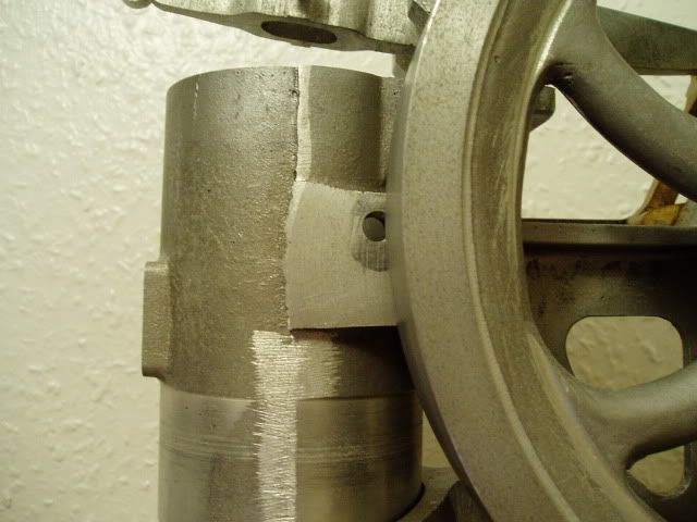
AS to the clearance...its more like 1/8" but in this case a miss is as good as a mile (photo 1). This morning I finished up the flywheel with the exception of polishing the machined surfaces. Oddly enough the plans specify a 3" dowel pin for the crankshaft, but after going through the bracket and leaving enough for the crankdisk, there is only enough to press into the flywheel about 1.150" of the 1.4" hub thickness. Its enough to hold the flywheel solid but as you can see in the second picture, it leaves about a 1/4" recessed hole on the exposed end. I am thinking I will make a brass cap for this which will look better than that recess and might even be a nice detail to go with the brass connecting yokes and brass pump, etc.


RE Build 047.jpg


RE Build 048.jpg
 
In the famous words of Ace Ventura:
"Like a glove!"

Andrew
 
Hi Bill.
Just watching, quietly. ;)

I held my breath for you, over the last few postings. Here's my part built, as received........

PB280001-1.jpg


Wishing you continued good luck, with the rest of the build! Thm:

David D
 
Looks like some interference there David. The hole location isn't super critical so maybe it can be plugged and redrilled just forward of the present location. Reducing the flywheel diameter is another option. From what I see on mine...the distance from the cylinder casting to the inner edge of the flywheel might also allow for a close nipple into the cylinder with an immediate "ell" avoiding the flywheel altogether.

Bill
 
Bill.
My thoughts are to plug, and re drill. No problem!
The flywheel o/d is also roughed oversize, only.

Story here...... http://madmodder.net/index.php?topic=3881.0

When I finally clear the tuit backlog, it is one of the first in line. But, I doubt that will be this year....... ::)

David D
 

Latest posts

Back
Top