Building a twin cylinder inline i.c. engine.

Home Model Engine Machinist Forum

Help Support Home Model Engine Machinist Forum:

This site may earn a commission from merchant affiliate links, including eBay, Amazon, and others.

Brian Rupnow

Design Engineer
Project of the Month Winner
Joined
May 23, 2008
Messages
14,978
Reaction score
8,270
Location
Barrie, Ontario, Canada
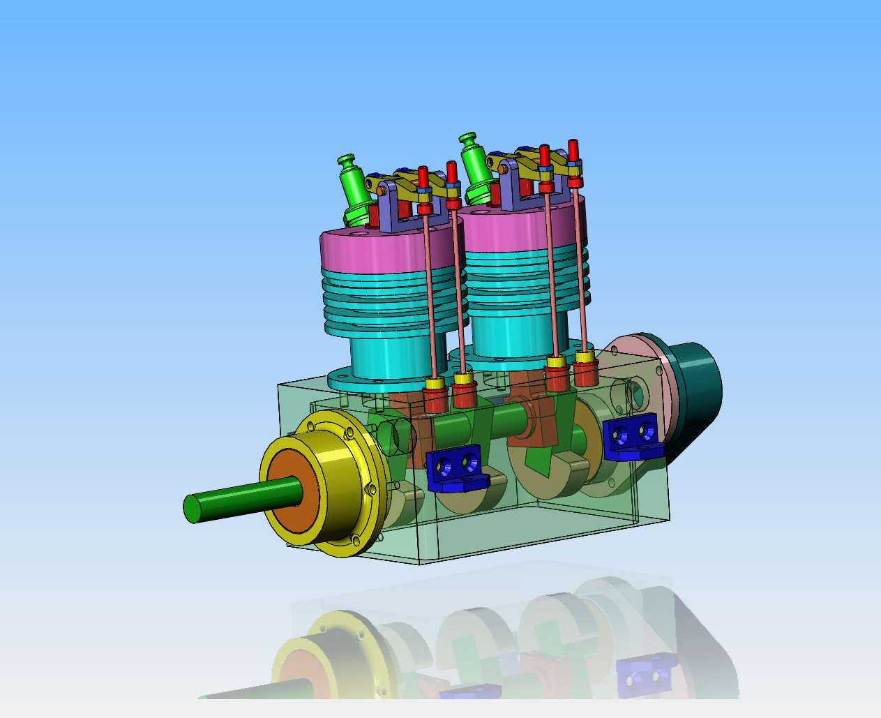
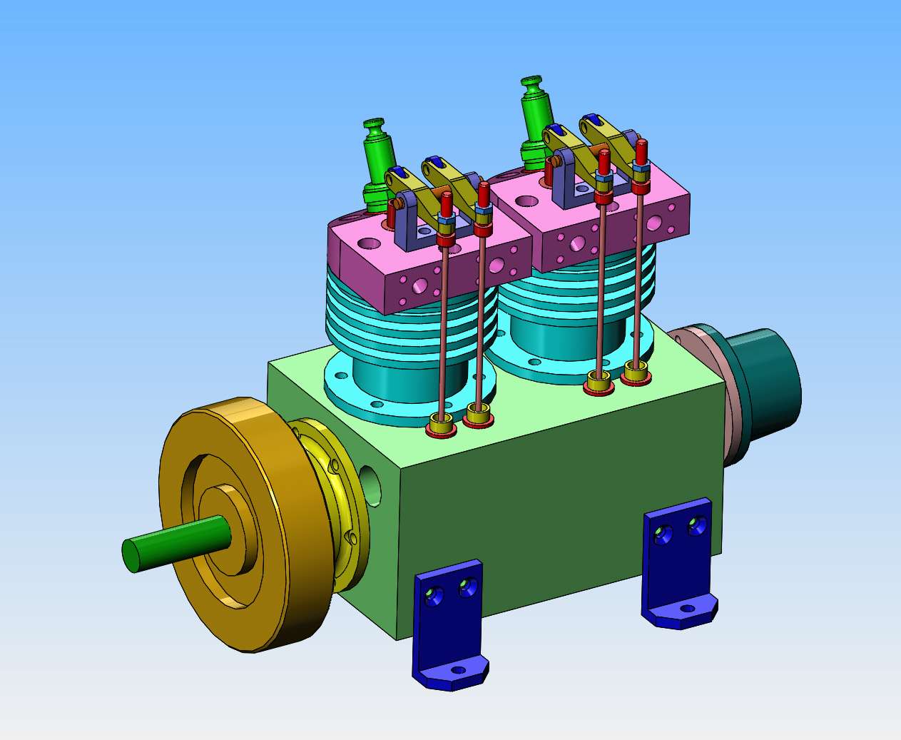
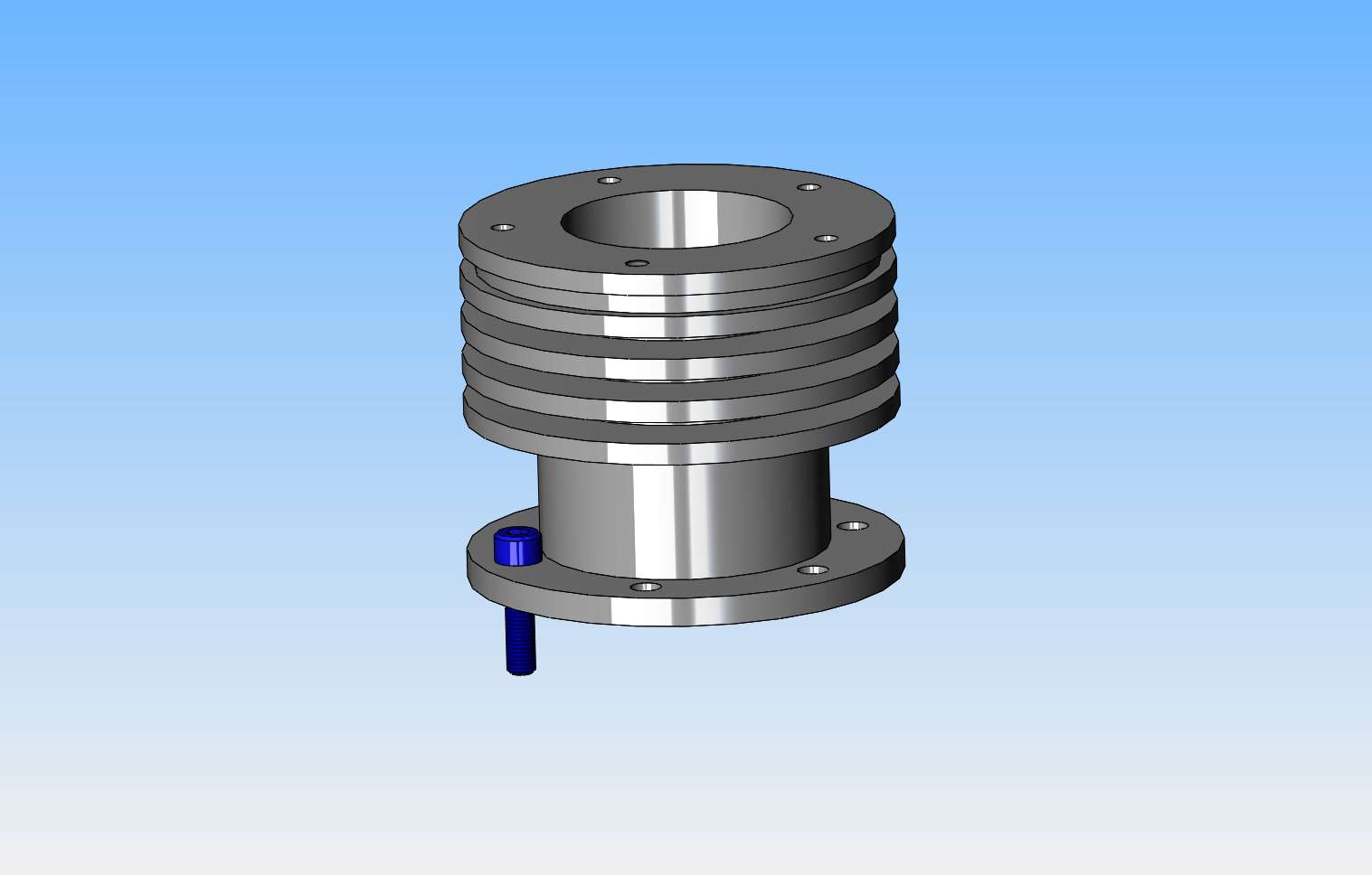
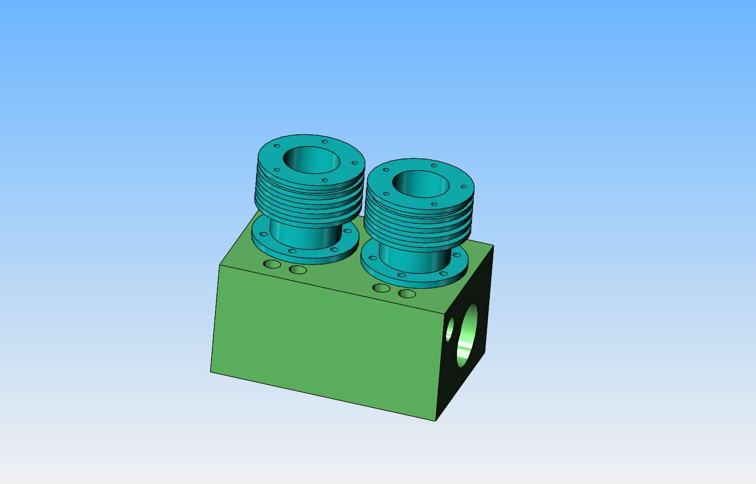
I have built single, opposed twin, and v-twin engines. I want to build an inline twin engine, and I have the drawings for Malcolm Stride's Bobcat engine. I build in the imperial inch system, and I will be upgrading the Bobcat engine to a 1" bore and using imperial inch measurements as close to the original drawings as possible, but keeping the same original stroke. This past year has been a very challenging one for me, and I have three engines designed and built that either didn't run well or didn't run at all. This has shaken my faith in myself, so I'm going back to an engine design that has proven itself to work well. I am just in the very beginning stages of this engine, so if you are interested, stick around. ---Brian
 
Can I suggest you also scale the stroke to the same proportion as you intend to scale the bore, same goes for everything. If not the resulting short stroke engine may need to be run faster and you said you wanted a slow runner

1mm on the original drawings scaled to 0.046" on yours would be the ideal way to treat everything just adjusting for stock material and fixing sizes.
 
Last edited:
I'm guessing this one? Obviously spark ignition. What was his approach on ignition system? Is that a distributer on the rear? Or pistons were on common CS throw so CDI with waste spark?
 

Attachments

  • SNAG-06-01-2024 1.34.42 PM.jpg
    SNAG-06-01-2024 1.34.42 PM.jpg
    208.5 KB · Views: 0
Yes, Jason, I will do that. The original had a 22 mm bore and a 20mm stroke. I will upgrade that to 25.4mm bore and 22 mm stroke. Petertha--Yes, that is the engine, and I haven't decided about the electrics yet.
 
Last edited:
Everything has to start somewhere, and seeing as the cylinder bore has changed a bit, and the piston stroke has changed a bit, then the cylinder will be the first candidate.-Because---the change in cylinder outside diameter will affect the center to center spacing of the two cylinders and this affects the main crankcase and the sump and the crankshaft and the camshaft. The original drawings asked for an inner sleeve of cast iron and an outer finned housing from aluminum. I find it a lot simpler to just make the whole cylinder out of cast iron.
iNpSGg.jpg
 
Because the outer diameter of the cylinders grew in size, the crankcase has to "grow" a corresponding amount. The crankcase model isn't finished yet, I have to add more pieces and see what interferes and what doesn't. Right now the crankcase is about 10 mm wider and 23 mm longer than the original crankcase design. Tomorrow I will get to add some more pieces and the holes to mount them. The trick here is deciding which dimensions change from the original drawings and which ones can remain the same.
TY2VcL.jpg
 
Well already you are deviating from a working design and missing points that may be what made it work.

The liner on Malcoms original sits proud of the jacket/fins and presents a small area for the head to seal against which is quite common practice on small IC engines. Yours will need a wide gasket and could be a source of leaks and therefore compression loss.

You also have the 5 hole pattern the wrong way round.

I've altered my scale factor to 0.046" to 1mm as I was thinking the engine was 20mm bore
 
Last edited:
Peter, two magnets set into a disc on the end of the crankshaft to trip a hall sensor and wasted spark.
 
There is another reason for using an iron liner in an alloy cylinder - that is the thermal properties of the alloy, which conducts heat significantly better than iron.
This may not matter if you only intend to run the engine for relatively short periods and without load.
If you are happy with one piece iron cylinders, it is quite simple to add the raised lip feature for sealing to the head gasket.
Here's hoping it all goes well for you, Brian!
 
Speaking of head gasket leaks, I have had good luck using O rings, esp on simple round cylinders. An appropriate groove is cut into the head about 1/2 the diameter of the O ring deep. Red
Permatex keeps it in position for easy head removal and replacement. I believe dragsters use them too except they are copper?
 
Peter, two magnets set into a disc on the end of the crankshaft to trip a hall sensor and wasted spark.
Jason, I'll take this offline to separate post if it goes sideways, but maybe there is a simple answer I'm not understanding. I'm about to embark on a boxer twin which I suspect has same layout (assuming inline twin has crankshaft throw with both pistons at TDC same time). My understanding: if there is one magnet on CS hub & its a dual fire unit (both ignition wires fire simultaneously with magnet signal) then timing would look like sketch. Waste spark safely occurs between EXH & INT because valve timing is phased 1 rev between cylinders. But if you put a second magnet/sensor on CS hub with this arrangement it will fire incorrectly no? Maybe you mean a second SENSOR seeing the same magnet... which means a second CDI/coil? or what am I missing?

1704648941458.png
 
..maybe I just answered my own question, at least pertaining to RCEXL type CDI ignition. 2 magnets on hub but N & S facing
 

Attachments

  • SNAG-07-01-2024 11.02.01 AM.jpg
    SNAG-07-01-2024 11.02.01 AM.jpg
    204.9 KB · Views: 0
Sorry peter, looked again and the magnet disc is on the cam so double ended coil tripped once per engine rev one spark going to the cylinder that needs to fire the other wasted. I was looking at a picture from my opposed twin version where I was just trying the gear cover for size and had it the opposite way round :oops:
 
Jason, yes magnet sensor on cam vs crank would explain it which is why I asked. And yes, even firing vs uneven firing module/setup setup is something to be aware of. My understanding is the RCEXL 'twin fire' even fire type module is used on 2-stroke opposed twins & just so happens to work on 4-stroke boxer twin with the waste spark as a byproduct with no adverse consequences. But any more cylinders (or throw layouts where pistons are not at TDC simultaneously) then requires 'uneven' ignition mapping however that is achieved. I'm still trying to get my head around cam driven sensor if CDI module has built-in advance retard because engine would see 2x ~30-deg, but lets save that for another post. I'm going to build a test rig so will have more to offer when the time comes.
 
Sorry Brian, People have to get on the band wagon on different ign's that are not required for the engine.
Thought Hall sensors needed to see a south pole to fire the coil. How does the N magnet work? Probably a dumb question--but?
The Rcexl ign unit required for the "N" magnet is the "LV" of multi cylinder ign system for uneven firing engines, ie:- "V" twins. They have a 4 wire pickup. South pole for #1 cylinder and North for all the others.
Cheers
Andrew
 

Attachments

  • 270.jpg
    270.jpg
    776.7 KB · Views: 0
  • 272.jpg
    272.jpg
    1,001.1 KB · Views: 0
And now you know how I spent my Sunday. Actually, the model is coming along very nicely. The cylinder head shape is going to change a bit. I haven't even thought very much about the camshaft yet. The position of the cam centerline is probably going to move a little bit, as I cut my own gears, and the pitch circle of the gears is what will determine the camshaft position---maybe.
oqGBiI.jpg
 

Latest posts

Back
Top