Weston Bye Magnetic Gear Clock

Home Model Engine Machinist Forum

Help Support Home Model Engine Machinist Forum:

This site may earn a commission from merchant affiliate links, including eBay, Amazon, and others.
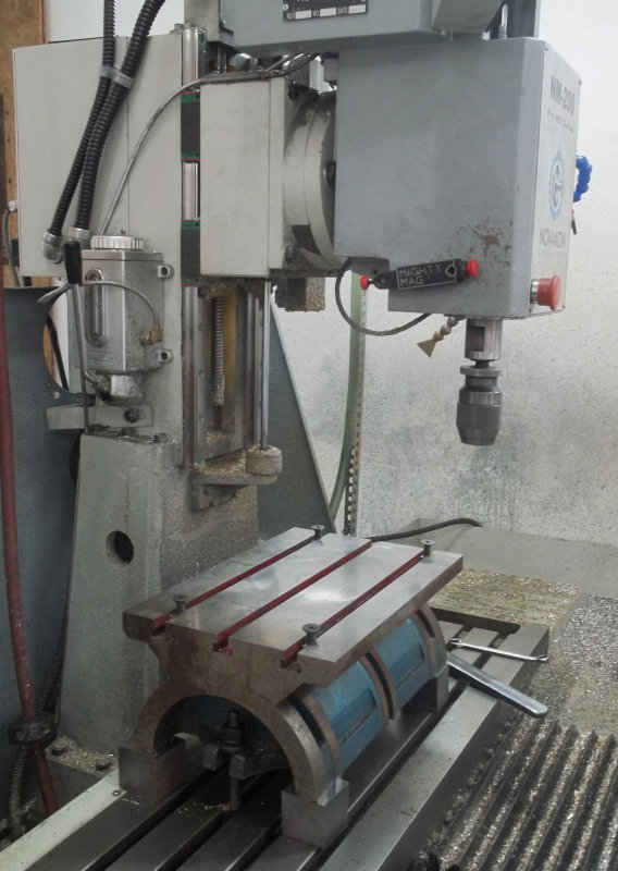
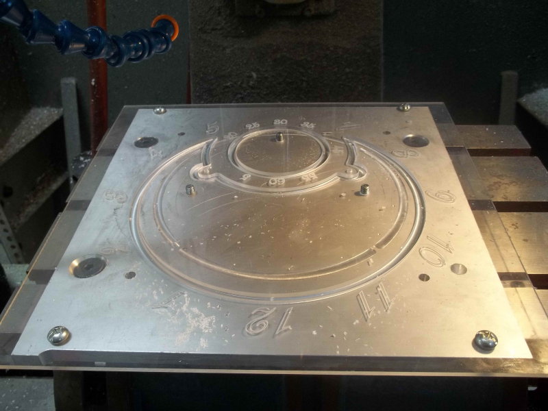
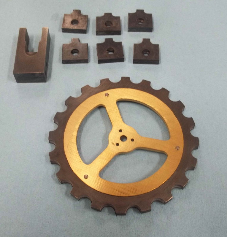
Machined the large wheel using a piece of aluminum as the fixture plate. For support I used a set of 12" vise jaws I got from Monster Jaws, in which I milled steps.

large.jpg


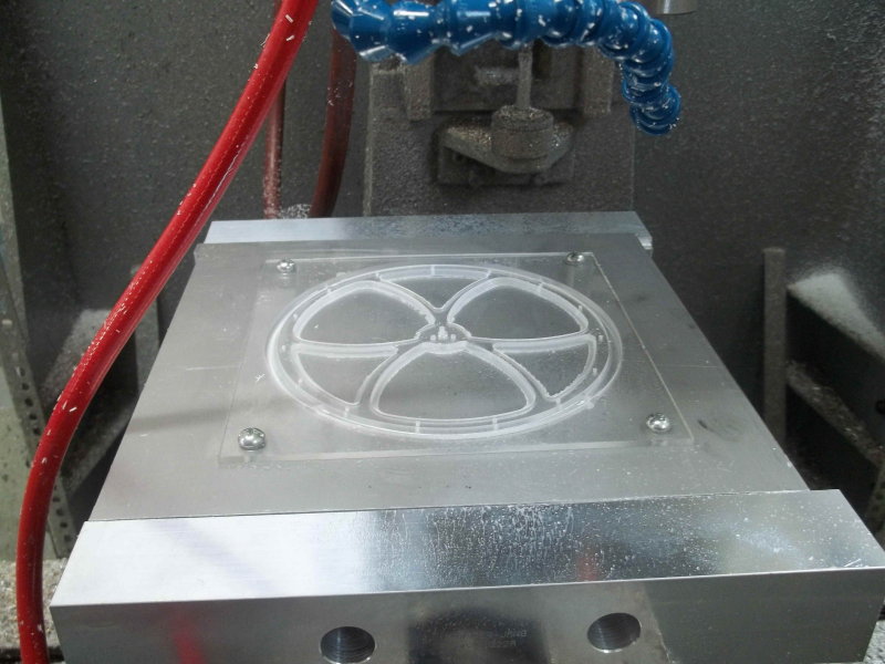
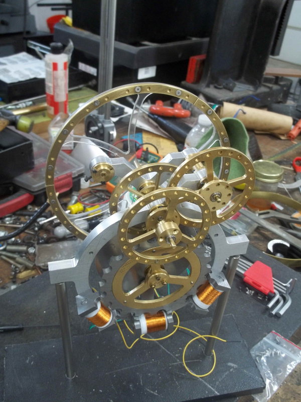
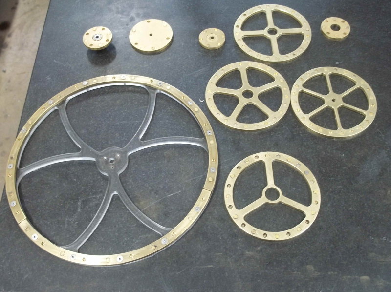
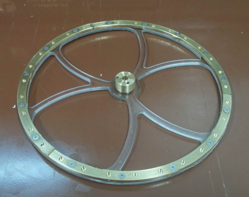
Then made the magnet pockets in brass strips that form the rim. I had to make these in 3 separate pieces in order to fit 4" wide brass sheet. The flat head 2-56 socket screws are stainless and thus non-magnetic. Since the wheel is now effectively 1/4" thick I made the brass hub thicker by 1/8".

large.jpg


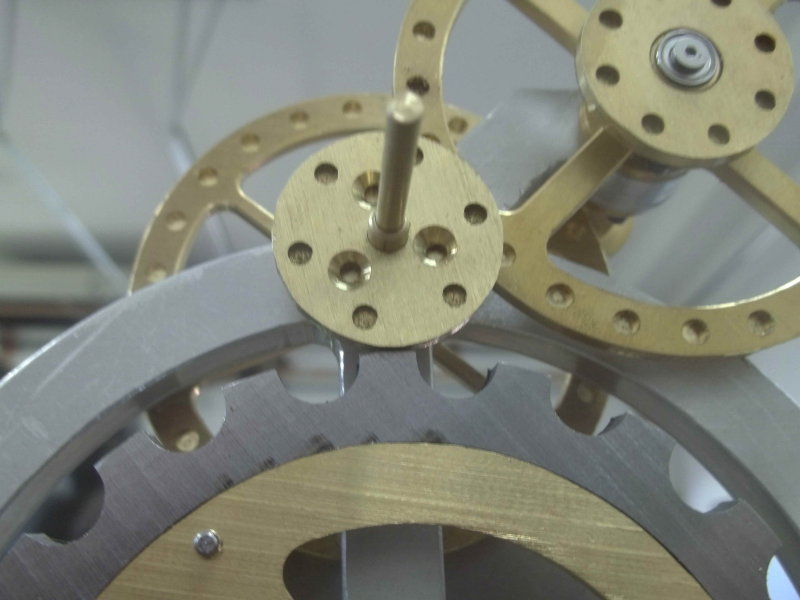
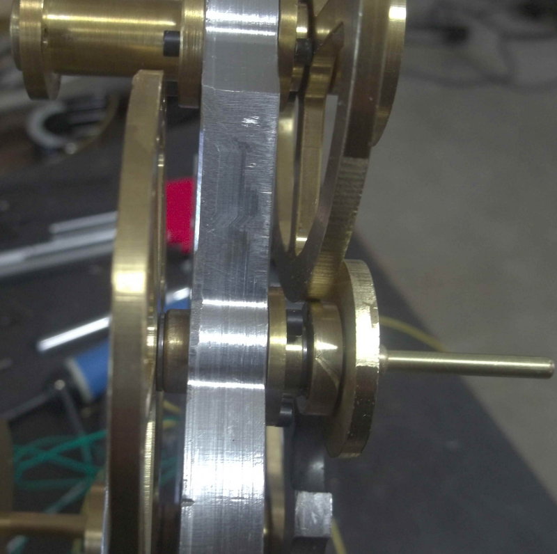
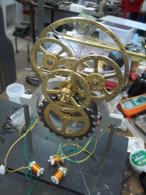
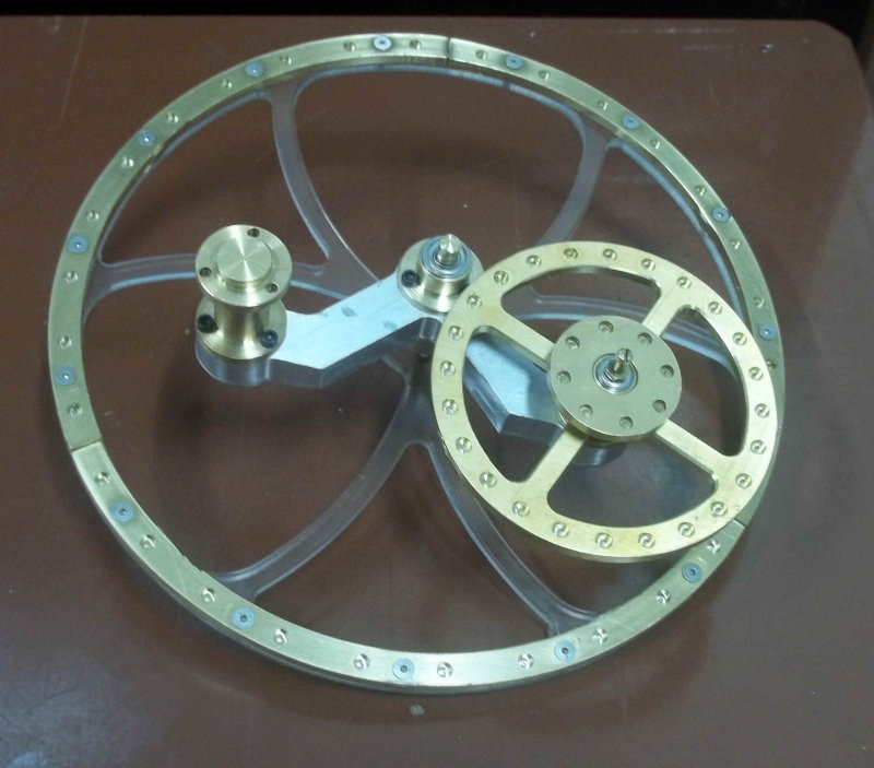
Then some test fits. I discovered that I'd messed up the small wheel that is connected to the large wheel's shaft by countersinking the wrong side, and also not milling a relief groove to clear the bearing. So that wheel will need to be remade. I also did remake the bearing carrier as I noticed it was drilled off-center.

The shaft lengths seem to be critical in getting the wheels to be close but not touching. The two intermediate shafts are easy to adjust, but the shafts that go through the bearing carriers are harder. I won't really know until I get everything assembled.

large.jpg
 
Remade wheel H, this time correctly plus the end of the shaft that attaches to it. I'll wait to make the head of the shaft that clamps the large wheel when I have all the pieces assembled and can check clearance.

Then I mounted a scrap piece of 4x4" acrylic sheet and tested out engraving the numbers that will go on the chapter ring. Used a 1/16" V-tip engraving bit I bought years ago but haven't ever used. Looks as if a .005" depth gives the look I want. It was hard to get a photo, but found this old wood background:

large.jpg


The acrylic bows when clamped in the vise, so I'll need to bolt down the big sheet on the fixture plate and try to it as level as possible to get even line widths. I might even reset the stock height for each number.

The font is French MT.
 
Maybe a few strips of double sided tape will help hold the acrylic down, make the strips small as they can be difficult to get off.

Paul.
 
Yes, but if the tape is not dead flat and covering the whole area the plastic will bend down between tape strips and with only .005 depth of cut your line width will vary a lot. This is a tough problem- the right way is a nice flat vacuum table, but those are crazy expensive and can take a long time to make.

I have tried a couple kinds of tape with varying success. I do not have a good answer.
 
I plan to drill and bolt the acrylic sheet to plate of aluminum that is pretty flat. Using 7 quarter inch screws and washers. That should keep the stock from bowing much.
 
Good luck. I have ruined a number of jobs with variation in depth of cut- when you are only .005 deep it does not take much to be noticeable. I recently bought a diamond drag engraver, which i have only used once. It did OK, not as deep as I would have liked but useable. It has the advantage that its depth of cut is spring loaded against the smooth nose of the tool housing.
 
I'll run a DTI over it when I get everything set up to see what kind of variation in surface I get. In the worst of cases I could reset the top of stock for each number.
 
Started the day trying to drill the mounting holes in the acylic sheet, but I've found that with the 12" aluminum jaws the vise interferes with the mill column on both the bridgeport and the CNC mill in order to get the full 11" Y travel needed to mill the chapter ring. After some cogitation I think I have a plan that will work. If it does I'll post the setup later.

Went back to the rotor test; enlarged the holes for mounting the electromagnets and moved the pole pieces closer to the rotor teeth. Finally I'm able to get the rotor to turn, although it's motion is jerky. Here's the test run:

[ame]https://www.youtube.com/watch?v=mf7RgXRrV60&feature=youtu.be[/ame]

The rotor wobbles on its axis so I need to investigate and see if getting a flatter rotation will make it smoother.
 
Since I found that mounting the 12x12" sheet for the chapter ring wouldn't work with the vise, I took a different tack.

When I bought the CNC mill in 2009, I got it with the tall column, thinking this would allow me to machine much taller pieces if the need arose. However, I failed to take into account that the Z travel is the same with either column, and as a result I could not reach the top of the vise jaws with tools even with the spindle all the way down. My solution for the past 4+ years has been to mount vises on a 6" tall cast iron tilt table. I was able to use the school's large surface grinder to grind the top of the tilt table, and it's been a quite good solution.

Now, with the vise removed, the top of the tilt table is still too low to machine flat stock fastened to its surface. My new solution for this was to take 4 steel blocks, all approximately 2" cubes, and use the surface grinder to make 2 sides of each flat and square to the other. By grinding all 4 blocks at the same time, all ended with the same height, to less than .001". Then placing these on the mill table and under the tilt table, the mill's spindle nose is less than 2" above the tilt table surface. This will be close enough to mill the chapter ring. I'll need to hold the engraving tool in a drill chuck as it's too short to reach still.

Here's a pic of the tilt table and steel cubes on the mill table. The tilt table surface is flat to within 5 tenths across the X direction, but the back surface is lower by 10 thousands compared to the front. Not normally a big problem in normal milling, but I'll need to shim the acrylic sheet for the engraving.

large.jpg
 
I'm able to get the rotor to turn, although it's motion is jerky....

Saw one of these clocks running at the show - I think once you get more of the gears on, the back pressure between them will dampen it quite a bit. The finished one had just a small amount of that wobble/jerkiness - I think it is the nature of the magnets. The large spacing on the first gear allows it to bounce a fair bit, the smaller gears with narrower spacing cuts that down. Any of you ex-science teachers out there should be able to give the technical reason (inverse square law on the distances, something like that? I was a software guy, this is a hardware problem!)
 
I got the fixture plate and acrylic sheet mounted to the table, so started the machining on the chapter ring. Doing the numbers first while the sheet is relatively flat, I measured the height at each position using a DI compared with the surface at 0,0,0. I wanted to ensure that the linewidths engraved were the same everywhere, and since the surface height varied by .01", I decided to use a separate machine OP for each variation in height. Basically, programmed a tool change for each different height, moved the spindle over the next number to be engraved, and set the tool height using a gauge block.

All was going well until, with 4 positions to go on the seconds dial, the drill chuck holding the engraving bit decided to open, flinging the bit across the table and snapping its point. Luckily no damage to the plastic sheet resulted. So I ordered a carbide 60-degree chamfer bit from McMaster, which will be long enough to hold in a collet, and which will allow me to finish the last engraving. In the meantime did the two center cutouts and shut the mill down with the spindle at the 0,0 position, so it will be ready when the new bit comes in.

large.jpg
 
Nice work. Dont you just hate long jobs like that where you have so many opportunities to screw it up :)

Are you going to try to edge light the acrylic sheet? If the letters are deep enough that should really make them pop out.. Maybe a couple LEDs mounted on the bottom edge?
 
While waiting for UPS to deliver my chamfer bit and let me finish the chapter ring, I decided to do a trial assembly of the parts I've completed. The photo shows everything but one of the intermediate shafts with two wheels.

large.jpg


Found some things to fix, mainly to remake the center shaft, where the rear part is about 1/8" too long. The front intermediate wheel also rubs the center portion, so it's diamter can be a couple of thou smaller. Also need to move the big wheel forward a bit and finish its shaft.

I'm debating whether to try to polish all the brass wheels before I glue the small magnets in their pockets. In any case, leaving on a 2-week trip on Saturday, so that won't happen before then in any case.
 
After 10 days away, including a visit to NAMES, time to get back to the clock. Put it all together for a fit check and discovered two tight spots with clearance issues.

The front 6 magnet wheel is very tight to the rotor, so dd a bit of filing.

large.jpg


And the front 24-magnet wheel is close to the collar of the center shaft. Took .04 off the collar to clear.

large.jpg


Then took it all apart for some finishing. I used a buffing wheel on wheel A to get an idea of how the brass would look polished, but I didn't care for the result. The brass stock has marks from the rolling mill that would be too hard to polish out, and besides most brass clock movements are not polished. So I just used some 600-grit paper on the 5 larger wheels to get a matte finish.

Then used some Casswell Perma-Blue to color the steel parts - rotor, damper frame, and the poles.

large.jpg


In most light they look grey rather than blue, but the coloring should prevent rust.

Finally, glued in half the magnets. All the alternating holes with the same polarity. The other holes will have the opposite polarity. That's the job for the next day, followed by reassembly to see if the damn thing will work.

large.jpg


Here's a pic of the chapter ring I finished before leaving on my trip.

large.jpg


As an aside, here's an interesting version I saw at NAMES. All made from Corian:

large.jpg


Seems any rigid, non-magnetic, machinable material could be used.
 
Finished gluing in the rest of the magnets and did a test assembly of the gear mechanism to test. Other than the large wheel, all the others seemed to hook up properly. The large wheel rim is separated too far from its engagement partner by about 1/8". This will be easy to adjust by facing off from its hub to move it closer. After disassembly, I need to finish up a few things before an actual run test.

large.jpg


1) Loctite the intermediate and minute hand hub to their respective wheels. They're currently a tight slip fit and can slip under any pressure.

2) Drill the end of the rotor shaft to accommodate attaching the second hand.

3) Machine the relief groove in wheel D, which I overlooked originally. My CNC mill is down for repairs, so I'll likely use the lathe or the rotab.

I found that the assembly should go like this:

1) Attach the bearing carriers to the frames.

2) Assemble the secondary frame completely but do not attach to the main frame as yet.

3) Assemble the rotor shaft components onto the main frame - rotor, damper, and magnet wheel.

4) Add front intermediate shaft and wheels to the main frame.

5) Attach secondary frame to main frame.

6) Finally add damper assembly and coils.

I found that using 82 degree flat head screws to attach the three wheels with the hex holes is probably not optimal. A countersunk socket head works fine, and there is no clearance problems. The issue with the flat screws is that the theoretical depth of the 2-56 head is .051". With a 1/16" hex boss on the shaft and a 1/8" thick wheel, it is quite tricky to get a precise countersink. Too deep and the wheel is loose, and too shallow the head protrudes. Since the countersink is on the opposite side from the magnet pockets, a second op is needed on these wheels. If the countersink is off center, even is the depth is correct, the screw head can cause the wheel to be cocked.
 

Latest posts

Back
Top