Weston Bye Magnetic Gear Clock

Home Model Engine Machinist Forum

Help Support Home Model Engine Machinist Forum:

This site may earn a commission from merchant affiliate links, including eBay, Amazon, and others.

kvom

Well-Known Member
HMEM Supporting Member
Joined
Jun 4, 2008
Messages
3,285
Reaction score
630
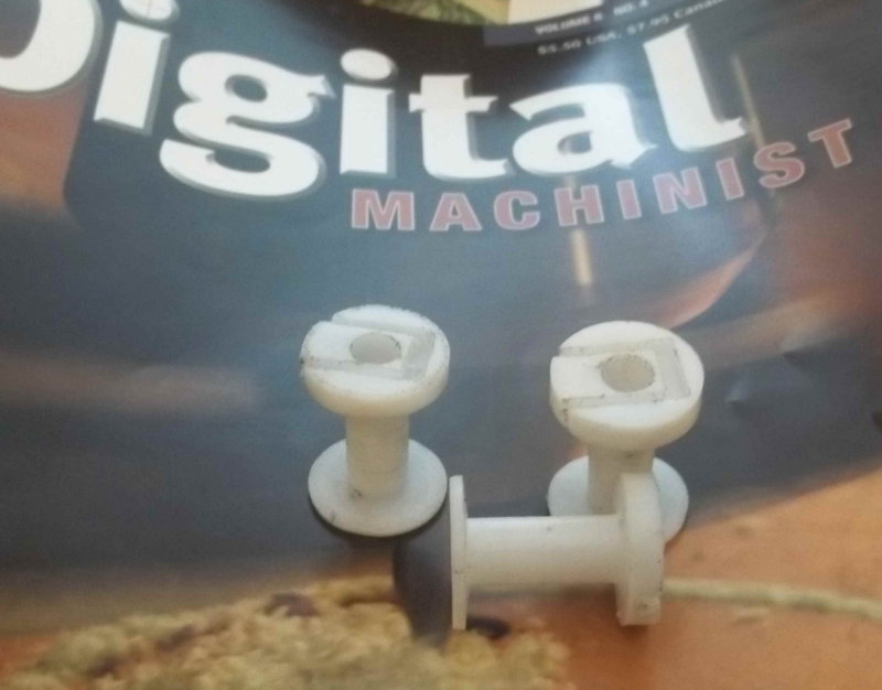
At Cabin Fever last year I bought the 5 issues of Digital Machinist where this clock's plans were published. Other than drawing some of the parts in CAD, I didn't do anything until this week, when I decided I needed another project. I spent the day making the first two parts, the main and secondary frames to which other parts are attached. I had bought a good-sized sheet of 3/8" 6061 aluminum, so cut out two pieces for the two parts.

large.jpg


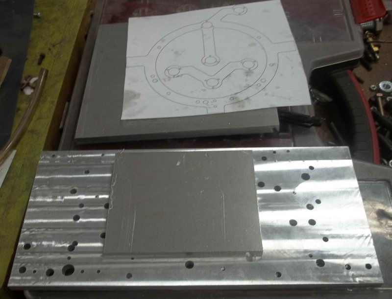
The stock for the main frame is 7.5" square and too big for the vise, so I planned to mount it on a well-used fixture plate. Most of the parts will be either milled CNC or turned manually. Here's a brief summary of how I'm doing the frame.

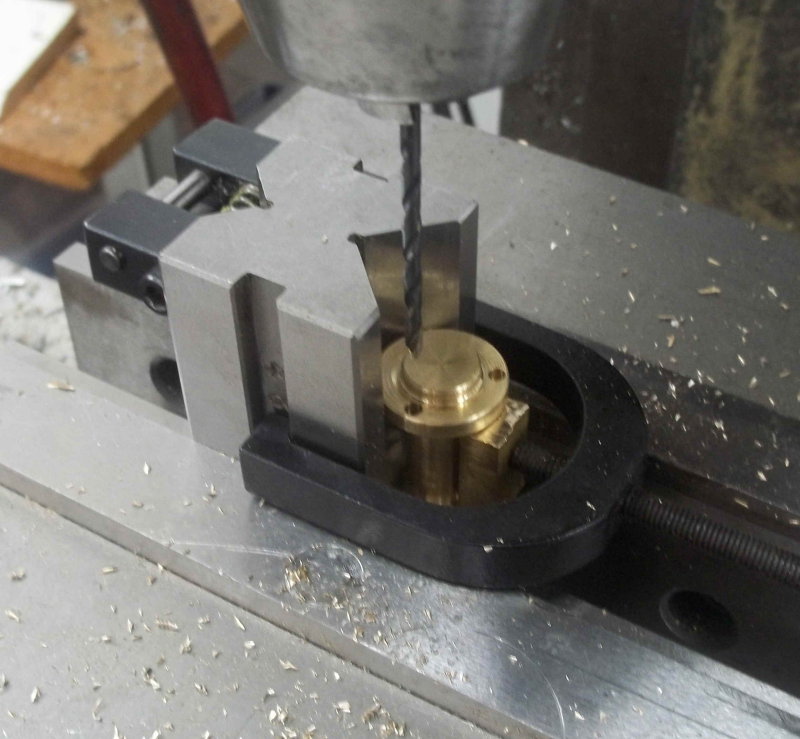
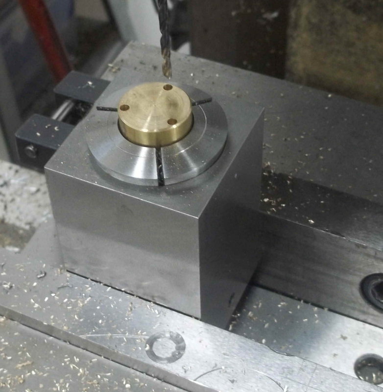
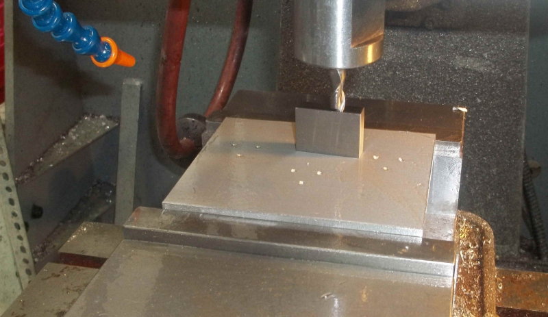
First find the center of the stock. Since this is a 1-off part, setting XY zero at the center is pretty easy.

large.jpg


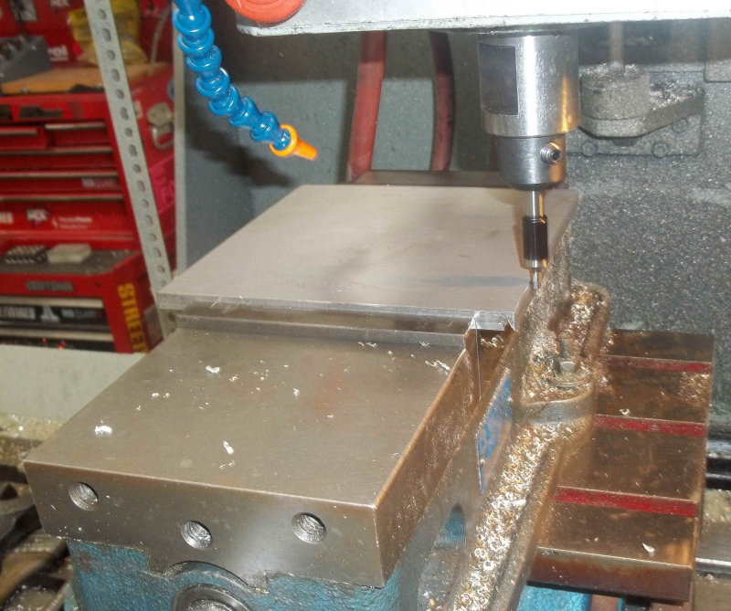
Next use the same CNC program to drill 1/4" holes in both the stock and the fixture plate.

large.jpg


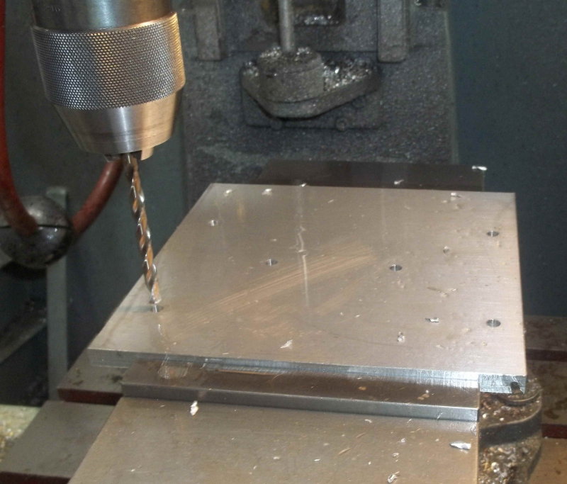
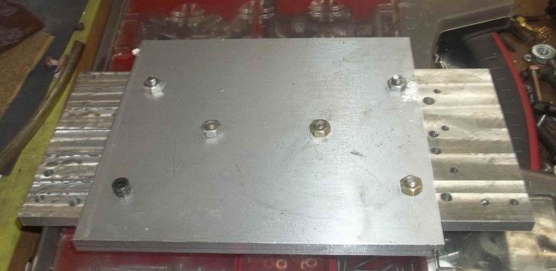
The stock securely mounted to the fixture plate ready for milling and drilling.

large.jpg


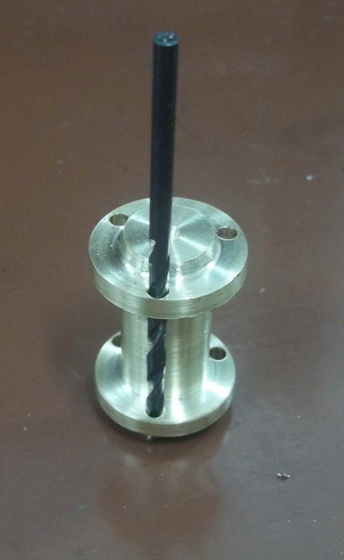
Using a gauge block as a height setter:

large.jpg


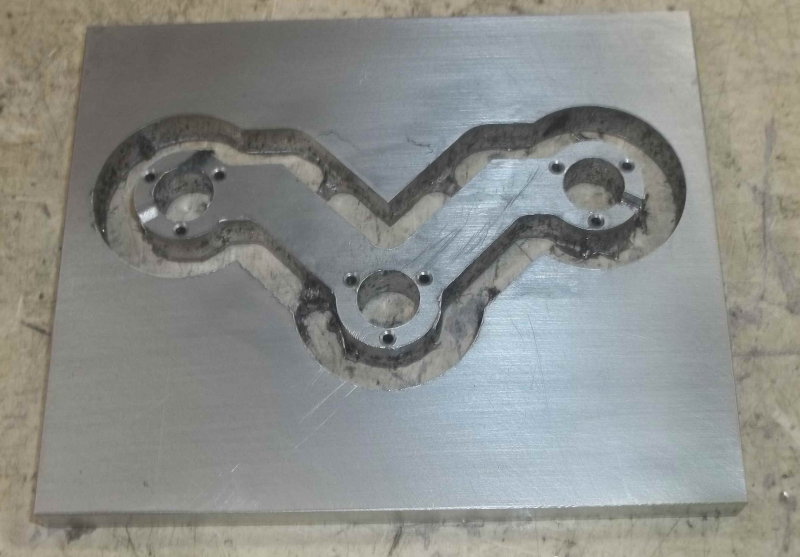
The subframe is milled from a 5x3" piece and needs no fixture. The CAM program provides 3 small "tabs" to keep the part from falling through at the end. These will be broken and the stubs filed off.

large.jpg


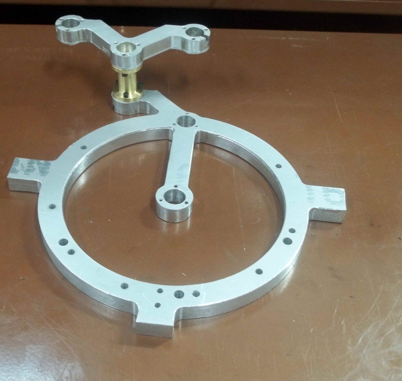
And the two frames at the end of the day's work:

large.jpg


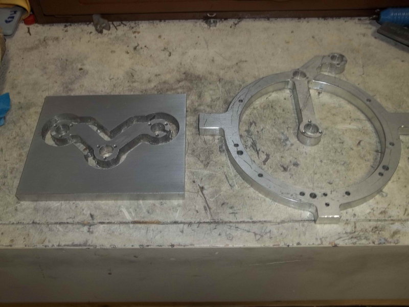
I still need to tap quite a few holes. I also modified the design very slightly. The holes where the shafts and bearings are mounted are drawn as .469" diameter. I plan to use hex-head 2-56 screws which have 1/8" heads. These would interfere slightly with the assembly (Weston used socket heads), so I reduced the bore diameter to .460".
 
Looking great. Welcome to the Weston Bye fan club. It will be a fun journey.

I got mine running good it took some fine tuning but not she has been running for about a 3 weeks now. I have not noticed it loosing or gaining time yet.

Dave
 
Will be following along to see how it goes ... read the articles with great interest but that build will have wait.

I hope you continue to report the progress on your switcher.:)

Pat H
 
I appreciate your posting how you’re building your clock . . . I learn so much form following such build-projects on HMEM.

One of your post states, “CAM program provides 3 small "tabs",” were used to fixture part for CNC machining. I’d like to learn more about this type of tab-fixturing if you’re willing. For this type of fixturing to function safely, how thick are the tabs? What is the width of the tabs? What CAM software are you using that already has this as a programming feature?

I look forward to your future informative postings.
 
Started on the magnet wheels today. planning to machine both the A and B wheels from the same stock with the same program. However, had some DOC errors on the A wheel, and screwed up the fix, so only got the B wheel done:

large.jpg


To save time and material, I'll do as many of the brass wheels as I can on the same stock, which I'm cutting from a strip 4" wide that I bought 5-6 years ago. For variety, the ABCD wheels will have 3, 4, 5, and 6 spokes respectively.
 
I appreciate your posting how you’re building your clock . . . I learn so much form following such build-projects on HMEM.

One of your post states, “CAM program provides 3 small "tabs",” were used to fixture part for CNC machining. I’d like to learn more about this type of tab-fixturing if you’re willing. For this type of fixturing to function safely, how thick are the tabs? What is the width of the tabs? What CAM software are you using that already has this as a programming feature?

I look forward to your future informative postings.

I'm using CAMBAM as the CAM program. For the cutout profile, you specify the number of tabs and the type, and then you can use the mouse to drag them around to where they're needed.

You can specify the height (measured from the target depth of the cut), and the length along the cut line. The types are triangle, square, and skip. I always use the triangle, which is created by the tool ramping up and down to create the tab. Square tabs are formed by rapiding up and then plunging back down, so needs a center-cutting bit. The skip type is used for laser/plasma cutters and just turn the cutter off and back on.

In the case of the wheel, I used 3 tabs. The material is ~.13" thick and my DOC is .15", so a height of .1" should leave a tab .08" high on the perimeter. I filed off most of it and will finish the edge on the lathe later. I used the default length of .1".
 
Excellent work so far. I will be following along as this is one of the projects on my must do list.
 
Clocks and clockworks have appealed to me since I was a kid. This is going to be an interesting project.

Incredible work so far. I can't imagine (me) doing this on manual machines

Cheers,
Phil
 
Next part on the list was the frame spreader that connects the primary and secondary frames. I turned it from some 1" brass rod; however, since a lot of the turned parts are .75" diameter or smaller I'm not going to waste material by using the 1". Ordered some .75" rod online.

The mounting holes on each flange need to be aligned, or else the secondary frame will be cockeyed. Drilling through both in one shot might have worked, but with no way to spot drill the inside of the flange I was concerned about the .096"drill walking. So I came up with this setup:

large.jpg


After drllling one end, I just flipped the v-block and used the (mirrored) coordinates for the other side.

large.jpg


Screwed it in for a test fit:

large.jpg
 
Machined the "bobbins" on which wire will be coiled to make the 3 electromagnets that drive the gear train. Used some .75" white acetal rod that I have on hand. These are just shy of 1" long.

large.jpg
 
They were fun to make weren't they. I love the brass parts it her will make for a great looking clock

Dave
 
I'm going to wimp out and have Weston wind the coils, and also buy the circuit board from him. I'll be mailing the bobbins tomorrow.
 
Kirk, I did the same thing. Im dont know much about those things and the price was right as well. Wes is a great guy to deal with.

Dave
 
I got my 3/4" brass rod yesterday, and had a little shop time today. Started the 3 bearing carriers. After parting and facing to length on the lathe, I needed to drill the same three 2-56 clearance holes in each. Here's my setup on the Bridgeport:

large.jpg


Then back to the lathe to do the first turning:

large.jpg


I'll be busy elsewhere through the weekend, so nothing more until next week.
 
I did finish the bearing carriers. I also heard back from Weston that my wound bobbins and circuit board had shipped. That was the good part. The bad part is that I received the magnets from United Nuclear, and they don't fit in their holes. I measured the magnets as .125", and then found that both my 1/8" carbide endmills measure .123. I have a HSS mill that appears to by on size and should work, but trying to set up to enlarger 150+ holes probably isn't going to fly. So I'll have to scrap all the magnet wheel done so far and remake with the larger edmill.
 
That sure does suck. I had the same issue with the first wheel I made. I use a 1/8 end mill but made the holes .127 dia. On all the others. The epoxy filled the extra.

Dave
 
Started the day by making the 'intermediate hubs'. These are turned from .75" brass round, and are straightforward. The only issue was drilling and tapping a 2-56 setscrew hole at a 30-degree angle between two mounting holes. I used my hex collect block to fixture this.

large.jpg


The finished parts:

large.jpg


Got the wound bobbins and circuit board in the mail:

large.jpg


In the afternoon I decided to save the 4 24-magnet wheels rather than remaking them. Cut an OD arc in vise soft jaws to hold them, and used the 1/8 endmill to locate one of the magnet holes. before tightening the vise. However, after using it to enlarge the holes they were still too tight. So I used a 1/16 EM to interpolate a .127 hole (still a little tight) and finally a .129 hole where the magnets slide in nicely.

large.jpg


Redid and A and B wheels today, and will attack the C and D wheels next time out. The 5 small wheels I'll just remake.
 
Spent the day making fiddly little brass parts needing multiple trips between the lathe and mill. I have worked out that certain dimensions are key:

.313" (5/16) is the OD of the smaller ball bearings, so any hole with that diameter gets reamed with the 5/16 oversize reamer.

.375" is the OD of the larger ball bearings, so holes get reamed oversize.

.188" (3/16) is the diameter of the large shaft and the ID of the large bearing. Need to check fit on the bearings. I intend to make these large shafts from separate pieces held together with loctite. This is because cutting a long thing shaft with precise constant diameter on my lathe is hard to do, and because I have brass rod of the proper diameter in stock.

.125" (1/8 )is the diameter of the small shafts and the ID of the small bearing. Again check fit.

It's hard for me to determine how critical any of the plan dimensions are from the drawings. I suspect I'll find out when I get enough parts made to start assembling. I am going to use loctite anywhere a press fit is specified.
 
Back
Top