Weston Bye Magnetic Gear Clock

Home Model Engine Machinist Forum

Help Support Home Model Engine Machinist Forum:

This site may earn a commission from merchant affiliate links, including eBay, Amazon, and others.
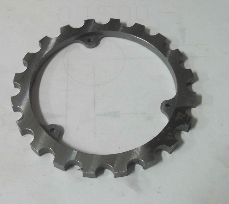
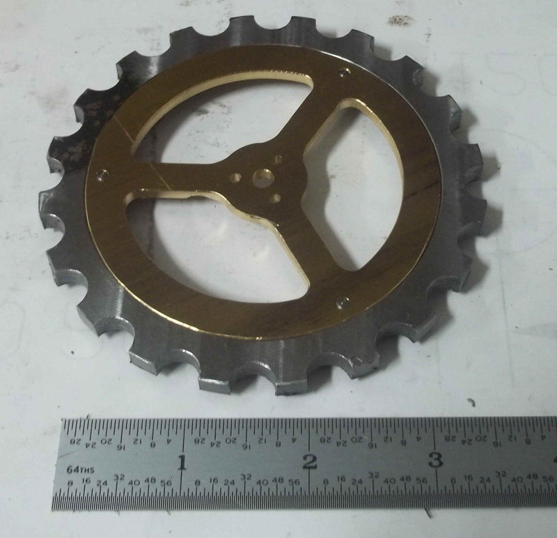
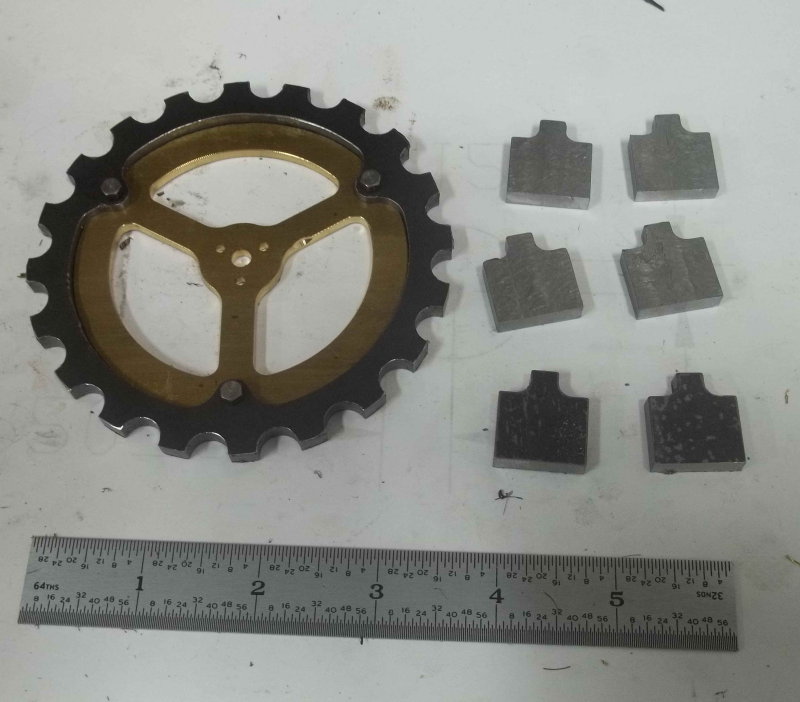
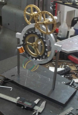
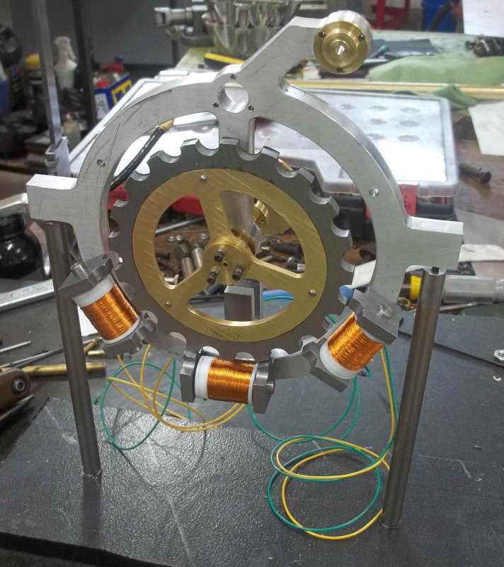
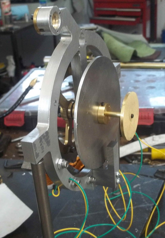
Here's where I am with the brass parts:

large.jpg


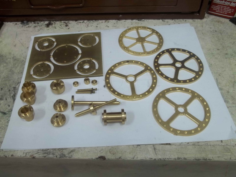
I have a few more to go, and then it's on to the steel rotor, the aluminum wheel too big for brass, and the chapter ring. Then it's time to try to put it together.

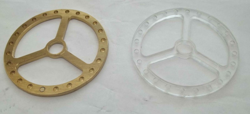
I recently acquired a vibratory finisher, and intend to try to polish the brass wheels with it. Have to buy some walnut shells for that.
 
Nice workmanship :):):).

I remember reading about the clock and hoping that someone would take it on ...

Very interested on how the vibrator finisher works ... can you show
us before and after pictures?

Thanks,

Pat H
 
What Pat said. Really interesting project. Thanks for the update

Cheers,
Phil
 
kvom,

Thank you for your post #21. Specifically, the showing of tabs to fixture five parts for CNC milling from a plate. It is good for me to see that this technique really works.

Some years ago I saw this fixturing method used to make a model engine flywheel from an aluminum plate;
http://www.cartertools.com/modengfly.html

This past year I took a course on CNC milling at a local community college. The lab assistant never had heard of tab fixturing and would not allow me to use it. I was going to make a base for a Webster engine.
http://www.machinistblog.com/free-plan-webster-engine-works-4-cycle-gas-engine/

My point is I learn from your postings on HMEM what I can not learn in a formal course.

Thanks again, and please keep up the good work.
 
Sometimes fixtures take more thought than the parts. For the wheel plate I just milled steps in the aluminum jaws I already had mounted on the vise. That way I didn't have to worry about the endmill doing through the bottom of the work and into the parallels. 12 different tools on that job. The cutouts with the tabs use ramping rather than plunging to get to depth. I use a center-cutting endmill but ramping is still easier on the tool.

I have some conical ceramic polishers that I will try out with the vibrator on some scrap pieces. I tried using them in a tumbler but found I'd have to run it for a week to see any results. The vibrator is supposed to work much faster,.
 
Today's output was to mill the rotor rim from some 1/4" steel plate.

large.jpg


The brass center will be attached using 5-40 screws.

The plans call for 3/16" thickness, but I'm going to surface grind off a few thou from each side and try the fit before going much thinner. The rotor will be gun-blued eventually.
 
Kirk. I made mine out of 1/4 stock with no issues. Parts are looking great.

Dave
 
Dave,

How did you secure the circuit board within the base? The 4 corner holes in the board seem to be 1/16" diameter, too small for 2-56 screws.
 
Made the rotor center section today and attached to the rotor rim with screws:

large.jpg


It seems I could mount it with either side facing the front of the clock:

large.jpg


The 6 pole pieces for the coils are show partially done. I had them in the vibratory tumbler for 8 hours, but it still didn't remove the mill slag from one side. I'll just make that the side facing the coils. The rest will be blued. Still need to mill and angle in the tops and drill/tap some holes.
 
Kvom, I just drilled them bigger to fit the 2-56 bolt. I will post a picture of my base tonight. I also put a switch and removable power cord.

Dave
 
I have enough parts to try some test assembly, so I cobbled together a temporary stand with 2 pieces of steel rod and some plastic.

medium.jpg


I finished the poles pieces and screwed two to the frame. The separation from the rotor looks a bit too much at this point, but without the coil actually mounted I can't be sure.

A friend of mine who is an electronics expert is going to help me get it wired up as soon as I have all the parts on the rotor shaft done. Seeing the rotor ticking over one blip per second will mean that the rest is just a matter of fitment.

As far as I can tell the only real tolerance requirements are that the magnet wheels are sufficiently close to the one they interact with to impel the proper motion. The other two main shafts may need some adjustment from the plans to do the adjustment since there is a wheel afixed to the end of each.
 
KVOM, You are correct that the steel wheel must be as close as you can get it with out hitting the coils. Looking great can't wait to see it ticking.

Dave
 
Bit of progress today. Wheeled out the surface grinder and ground the rotor on both sides, so it's ready to be blued. Also ground the 5 small wheels still lodged in the original workpiece as well as the rotor center.

Then finished drilling the pole pieces and did a fitup on all 3 sets. The separation from the rotor is about .06", probably too far(?). Options for getting them closer are either to remake them, or to make the mounting holes in the frame larger. An option I rejected is to reverse them and redrill/tap the mounting holes slightly lower down, but that would leave the original holes exposed.

I also discovered a non-obvious fact. The little spacers in the accessory hubs need to be loctited inside the hubs. Otherwise the wheel assembly and hubs can slide over the bearings and shaft. The through hole in the spacer should also be drilled larger than .125 to be sure to clear the shaft, otherwise it will rub.
 
After a weekend away from the shop, I made a few parts sufficient to mount the rotor shaft securely. Then attached the coils and pole pieces to the frame. At this point, I should be able to hook up the circuit board and power supply, and see if the rotor will turn over. It should turn at 1 RPM, as it drives the second hand directly.

large.jpg


I ordered the N52 magnets for the damper circuit today on eBay, so they should be here by the weekend. I'm still working on the best way to machine the damper disk, which is 3.9" diameter but onlyt 1/16" thick.

I also decided to try to (try to) make the large magnet wheel from clear acrylic, and the chapter frame from acrylic as well. I ordered a couple of 12x12x1/8 sheet from McMaster this morning.
 
This morning I made the damper disk for the second time. My first try was from 1/8" brass that I tried to mill flat to 1/16", but the result was uneven and had a twist. This version is made from 3/32" aluminum, thicker than in the plans but should be workable. Disk diameter is 3.9".

large.jpg


In operation the steel fork at the bottom contains 2 neodymium magnets on either side of the disk. When the rotor turns along with the disk, the magnets generate eddy currents that act as a brake to keep the rotor from overshooting. I'm waiting for the magnets to show up in the mail, and the damper will be easy to test. Presently when I spin the rotor it will keep going for several minutes; with the damper in operation it should slow much more quickly.
 
I made my disk from 1/8 thick and it works great. I just modified the bracket that holds the magnets. The disk does not have to be solid you can cut holes in it just leave about 3/4 of inch rim. Sure is looking good cant wait to see it running

Dave
 
I received the neodymium magnets in the mail this morning, and inserted one into the eddy current bracket. Even without the second one the braking is quite pronounced. If I give the rotor a good spin it stops within a single revolution. I'll need to insert the second when the rotor shaft is disassembled; it might not even be needed.
 
Today I took the frame/rotor and PCB to my friend's place, where he soldered push-on terminators to the coil leads and right-angle pins to the PCB. Then when he tested the recommended JameCo wall-wart, which supposedly output 12V, we found it was giving 18V. So then it was off to Radio-Shack to get another type. Back after lunch, we measured 13.5V output, so he soldered on the terminators and hooked everything to the PCB. With the power attached, we got no movement on the rotor.

He used a logic probe on some of the board leads to determine that its output seemed correct, each firing every three seconds. After a nit of head scratching, we tested the magnetism on the pole pieces and got very weak force. It turned out I'd used some drill rod for the coils that is only weakly magnetic.

Went home, found some steel rod that attracted the damper magnets strongly, cut to length, and replaced them in the coils. After hooking it all up and plugging in the power, I got motion of the rotor. Unfortunately that motion is jerky and mainly in the wrong direction, So more fettling is needed. I suspect that the separation between the rotor lugs and the poles is too large, and I'll need to remake the pole pieces.

Here's a shot of the board and its connectors.

large.jpg
 
Kirk, I had some issues with the rotor as well. Instead of remaking the 6 steel post I made the holed on the main frame larger so I could adjust the coils to the rotor. I set mine with a business card. When you checked it did you have the other gears attached?

Dave
 
Just had it with the rotor and the rear wheel. I may try enlarging the holes. Today's project is a test for making the large wheel from acrylic. Going to make an acrylic version of wheel A on a small piece first.

*** some time later ***

Here's wheel A made from 1/8" cast acrylic sheet, using almost identical machining. No ne of the operations resulted in any chipping of the edges. I used a 1/4" HSS O-flute mill, a type of cutter recommended to me on another site. This tool has a single cutting edge and a very wide and long flute. The 3 inner pockets were machined with this bit. The outer rim I cut with a 2-flute carbide EM. This left a sharper burr, but being plastic is not a real issue. The inner pockets were chamfered, and this too worked well.

The photo shows the brass and plastic versions.

large.jpg


I now feel confident about making the large 7" diameter wheel from acrylic, as well as the chapter ring.
 
Last edited:
Back
Top