BillC said:
Bez,
The block is a complex casting...The core needed is almost as intricate as the outer block.
Thanks Bill
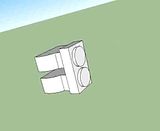
I did a concept sketch of the block core a few weeks back, which I thought would look something like this;
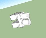
If its way off, now would be a good time to find out. the rectangular section is the water jacket, the cylinders are long but its nearly all core print.
BillC said:
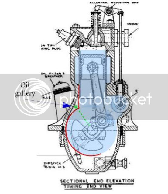
The oil gallery under the cam is due some scrutiny. That is an area that I would change to have all of the oil lines inside of the castings and no external lines except to and from the pump and you could do it quite easily in your instance where you are making your own patterns....
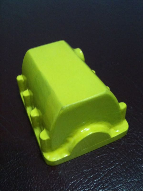
I would like to look into that, on the subject of oil - in particular, the filter and it's connection point. this is not looking too good with this pattern as I thought I could get away with a one piece pattern.
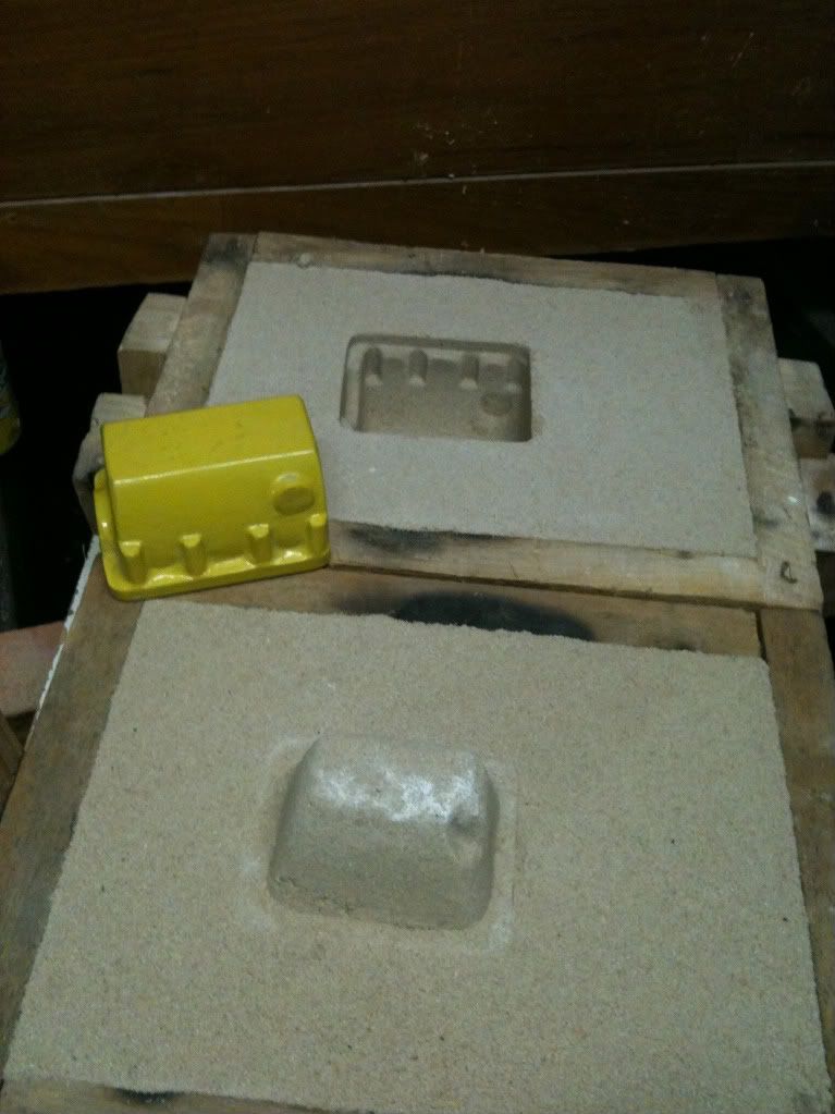
I have rammed up a test mould and the out side of the sump slides out real nice. The sump's inside with its internal filter connection point is a whole different story. In spite of the heavy draft angle it is still to deep for the pattern to slip off without braeking off the core. It looks like I have little choice but to make a separate core. not a bad thing overall as I can make parallel sides on a separate core, and that should overcome the oil filter connection issue.
BillC said:
I made a windage tray for the bottom end
My ignorance to the fore here, what is 'windage' ? ??? ? I was expecting this thing the burn gas not make it. :big:
BillC said:
I will be happy to take some photos of this 'nude' block casting if you would like.....Sometimes a drawing just doesn't do it!
BillC
Please hold that thought, I might just cash in the offer if it all starts to go a bit pear shaped here.
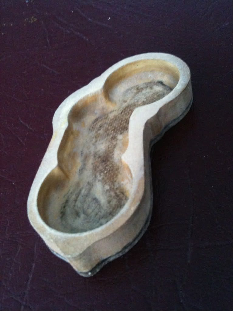
although thinking about it - in cross section, the bottom half of the block and sump is supposed to look a bit pear shaped anyway,
and I got the Timing Cover started, but there is still lot more work to be done there yet.
Bez


") This engine was a joy to complete and has been a joy to run - you're gonna love it!
This engine was a joy to complete and has been a joy to run - you're gonna love it!