Wallaby 30cc 4 Stroke

Home Model Engine Machinist Forum

Help Support Home Model Engine Machinist Forum:

This site may earn a commission from merchant affiliate links, including eBay, Amazon, and others.
I agree with Dave. It looks like you could have a problem putting it in that area. While you're making the patterns why not run a longitudinal boss along the outside of the block in the same area. This way you won't have to infringe on the internal room and it will give you enough meat to drill, even if the drill does wander a bit.
gbritnell
 
Hi George,

Maybe up a little just to the right of the breather cap maybe?

It's a tough call. Not a lot of room!

Dave


Hi Guys

Thanks for the feed back. Some good ideas there.

I've been stranded in T-ash-mania all week, just got back last night. :big:

I like the idea of adding a gallery to the outside. i think I might go that way.

Pete, We should be able to pour a casting this week sometime.
 
A few posts back I made a trial mould for the sump and found I needed to build a separate core box for the inside of the sump.
I haven't taken any pix of the core box yet, but you'll see how I did when I get some.

I got a full day in the shed today and Pete got his long awaited look at some liquid metal as we set about to pour a casting for the Wallaby sump. ;D

Unfortunately my choice of gate location wasn't suitable for this shape casting so the first casting was a miss pour. I tried to feed the gate in from end and with the thin walls it just froze up before the mould was full. :-[

Any way the position of the gas holes showed where the gates needed to be so a second pour gave a better out come.

Disappointing for Pete because he had already left.

Any way here's how things turned out.

sumpcasting.jpg


sumpcasting1.jpg


Bez
 
Thanks for the pictures Pete :bow:

It's hard to do a self portrait while your trying to maneuver a bowl of liquid Al. :big:

I might just add a few words to explain whats in the pictures and how they all fit together.

This sump pattern is a split pattern, which means it separates into smaller parts and part of the pattern is above the parting line in the top flask(the cope) and part of the pattern is below the parting line in the bottom flask (the Drag).

Here the top half of the split pattern is being rammed up in the cope.

5876413879_2285d2ca4a.jpg
 
When the cope is turned over ( it is now upside down) and the second half of the split pattern can be added.

5876414093_33a59c87b2.jpg


In this case the second half of the pattern consists only of a core print to locate the core that makes the cavity for the inside of the sump.

5876975498_3b40cb2987.jpg
 
The core is made of sand in this case it is a greensand core so there is no need to bake it.

To make the core the required shape a core box is required.

In this picture you can see the two halves of the core box and the core - note the truncated 4 sided pyramid that matches the core print of the split pattern seen previously.

5876413789_f6e740786a.jpg
 
This next photo shows the core located into the core print in the drag.

5876975904_a8eee88161.jpg


After the pouring sprue and runners have been cut out in the cope, the pattern can be removed. (note: this casting is just a little too thin in the walls for this runner to properly fill the mould.

5876414661_8567351e13.jpg


The Cope is then lifted onto the drag ready to pour

When the melt is almost ready to pour - all the lifting hardware is preheated to help keep the metal liquid as long as possible during the pouring operation.

5876414835_def4cd8e30.jpg


Next step is to fill the mould with metal

5876415309_6bed83bfca.jpg


OK ! AND?

;D


How'd they turn out..How'd they turn out? th_wwp

Dave
 
Hi Dave

That last series of photos was way out of chronological order - Sorry about that.

The outcome was posted first in reply #43.

Although the results are much better than the miss pour Peter saw, I'm still not fully satisfied with the gating for this casting, because, if you look very critically at the outside of the casting there is evidence of a cold shut running horizontally from the oil line boss. This occurs when the metal traveling in two different paths arrive at the same place at different temperatures. :-[ In future moulds I will vent the mould better and gate from both sides to flood the mould quicker and this should eliminate this issue.

Bezalel said:
A few posts back I made a trial mould for the sump and found I needed to build a separate core box for the inside of the sump.
I haven't taken any pix of the core box yet, but you'll see how I did when I get some.

I got a full day in the shed today and Pete got his long awaited look at some liquid metal as we set about to pour a casting for the Wallaby sump. ;D

Unfortunately my choice of gate location wasn't suitable for this shape casting so the first casting was a miss pour. I tried to feed the gate in from end and with the thin walls it just froze up before the mould was full. :-[

Any way the position of the gas holes showed where the gates needed to be so a second pour gave a better out come.

Disappointing for Pete because he had already left.

Any way here's how things turned out.

sumpcasting.jpg


sumpcasting1.jpg


Bez
 
Its time for another post.

I've been working out how to build the core for the engine block.

blockcore006.jpg


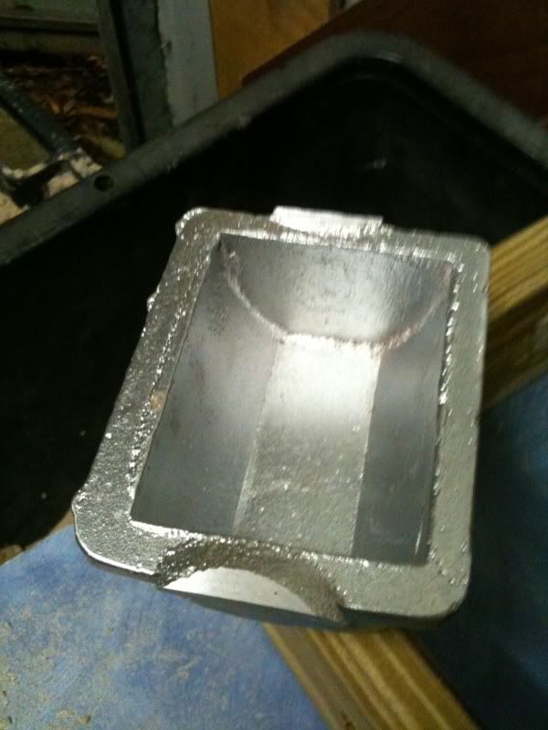
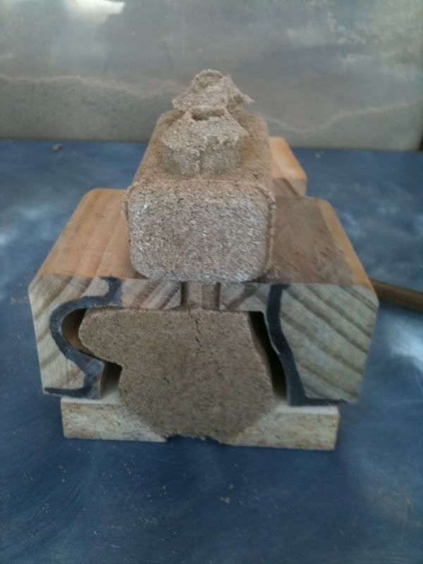
A bit of a challenge because there is a crank bearing seat across the middle of the block separating the two lower halves of the block. each of these separate cavities is connected to the water jacket cavity by a thin length of cylinder. I was a little concerned that this core may not support its own weight in the mould. I think its sorted now.

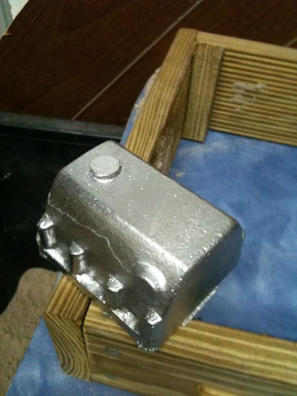
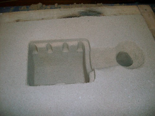
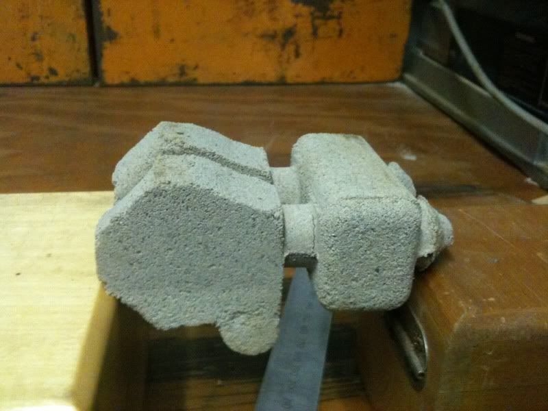
Here is the core supported by the core prints at the top and bottom of the block. {after baking}

blockcoresusspensiontest.jpg


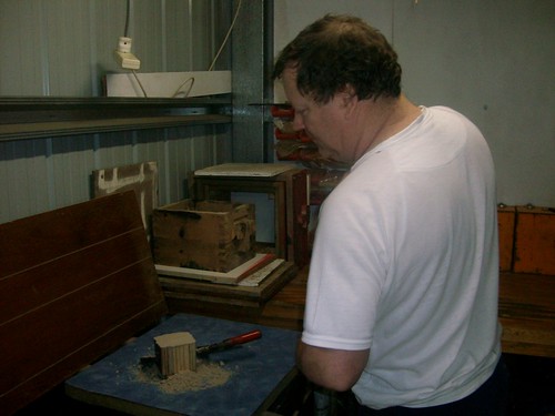
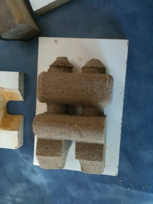
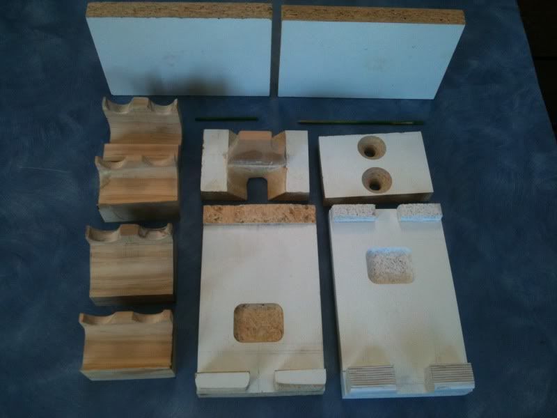
here is the sequence of events that shape the core in the corebox.

blockcore010.jpg


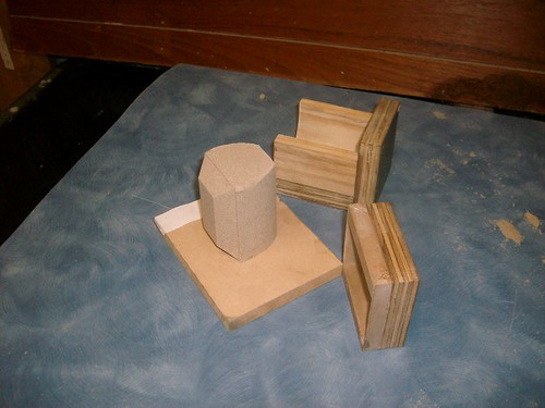
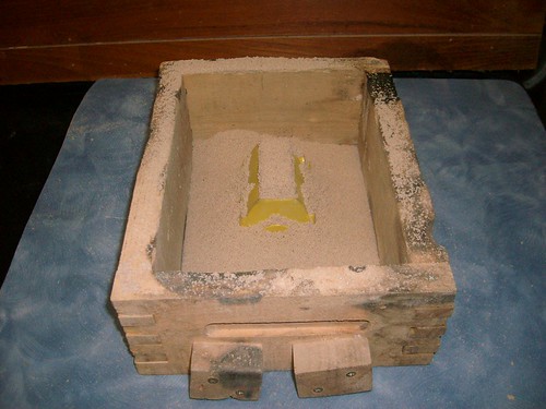
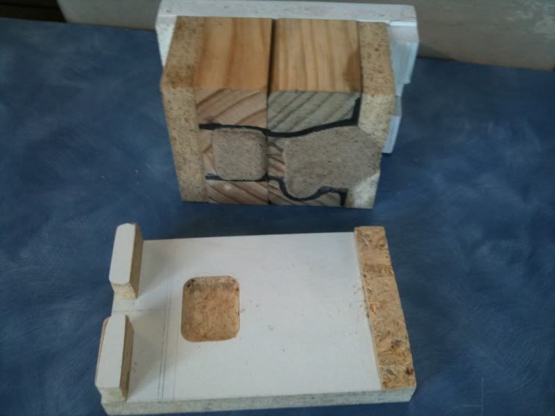
The core box is made up of 4 shaping blocks 2 core prints and the 4 outer boards that hold every thing together.

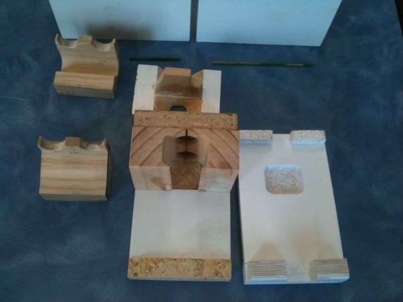
The top core prints and water jacket former are placed in the box first.

blockcore002.jpg


Next the two formers for the lower half of the block and the bottom core prints are added to the box.

blockcore007.jpg


Then two of the sides are clamped into place to line everything up.
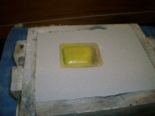
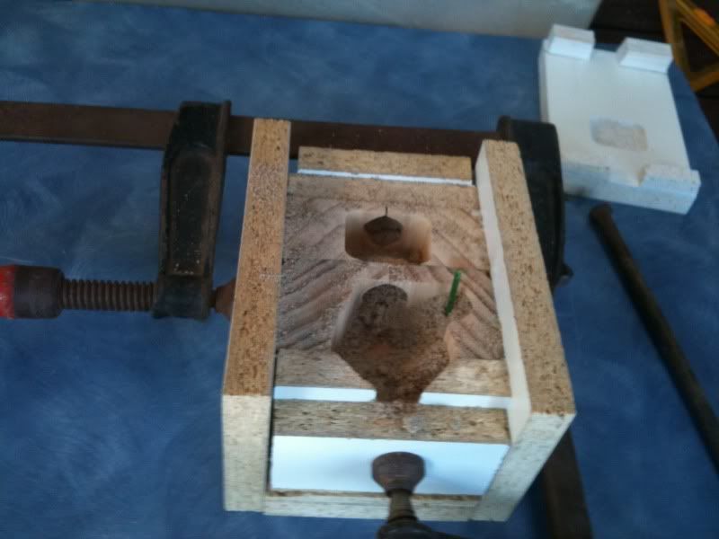
The camshaft cavity can't be accessed after the box is closed so it is rammed up while the box is still open on one side. a small wooden reinforcing stick is added during ramming to give some green strength to the core before baking.

blockcore012.jpg


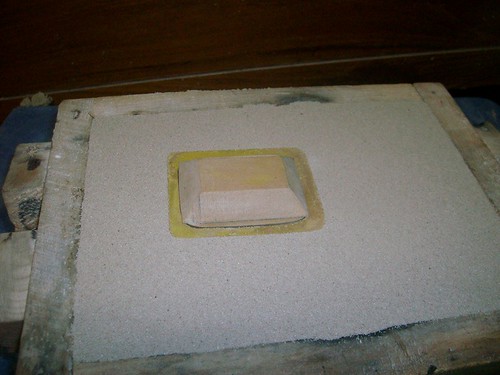
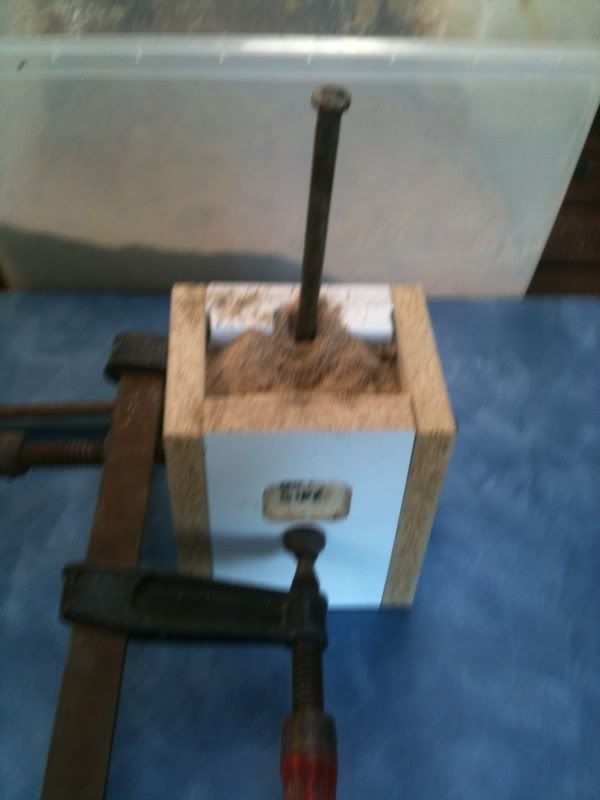
The box is fully enclosed and the core sand rammed up with a 9" nail

blockcore009.jpg


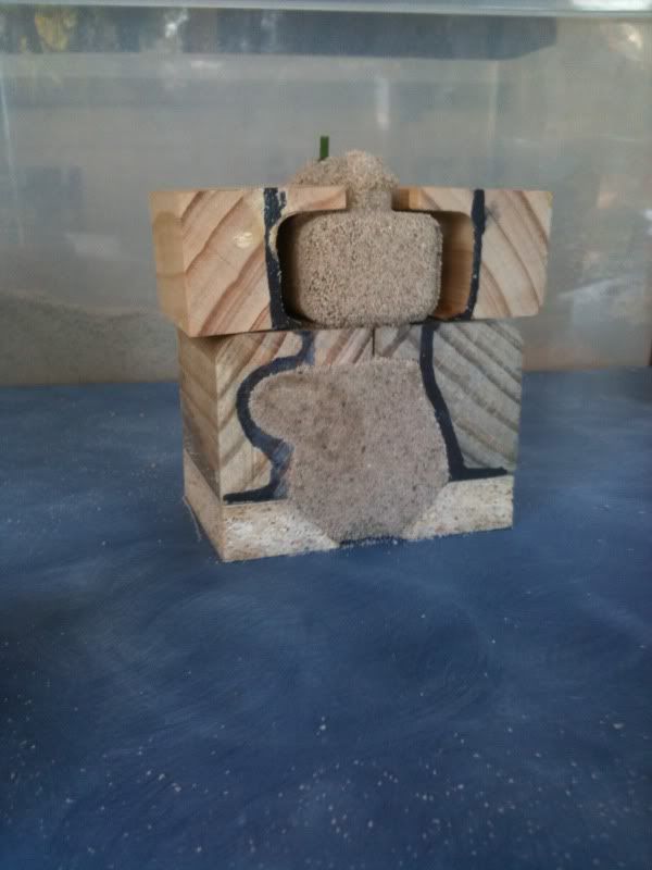
when its all rammed up the clamps are removed and the sides taken off.

blockcore003.jpg


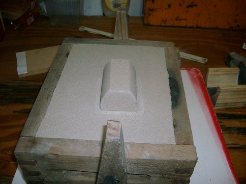
The top core print former is rapped free and removed followed by
the water jacket formers.

blockcore001.jpg


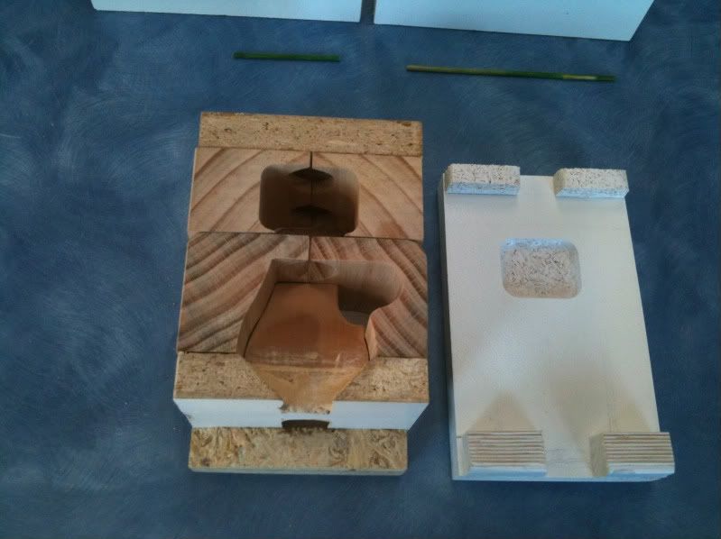
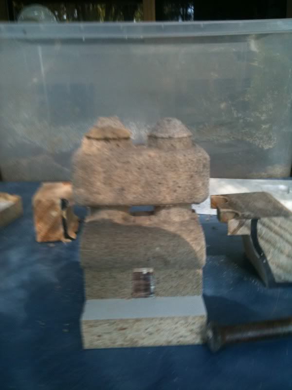
Next the lower formers are removed.

blockcore013.jpg


The bottom core print former also contains the former for the center crank bearing seat. so when that's off - its ready for baking.


blockcore008.jpg


This is my first baked core so I followed Tel's already proven formula for core sand - with flour and molasses.

Thanks Tel, that stuff is GoooooooD - I think a few bricks of that will be going into the next dunny I build - That aught to stop the emus kicking it over :big:

 
Thanx for the informative core build up pictures and explanation. Great work and keep the pics coming. What sort of casting sand do you use?

Brock
 
No rest for the wicked.....got machines to design.....
 
ShedBoy said:
Thanx for the informative core build up pictures and explanation. Great work and keep the pics coming. What sort of casting sand do you use?

Brock

Hi Brock

My normal casting sand is a fine white (the likes of which is preferred for kids sand pits)
to this I add 8-10% foundry grade sodium bentonite "TRu Bond" is the brand I use.

Although in Queensland you don't have to buy it - on the unsealed clay roads, on the west side of the great dividing range its just white bull dust.
You can also buy it as a stock grain feed supplement at any produce store "Tru feed", its the same stuff just a bit granular - their no different at all when wet.

For the moisture content I use an old spray starch/ Windex bottle to spray and mix till it feels right. A key safety matter when it comes to moulding sand - If the sand sticks to your hand when your mixing it, then it is probably too wet to use without the risk of a steam blow back and that's not good for anyone in the vicinity.

For the core sand I used the formula Tel described in reply #4 on this thread

http://www.homemodelenginemachinist.com/index.php?topic=1461.msg10683#msg10683

I hope this is helpful.

Bez
 
Hi Bez
does this mean we can eat the core after its been poured?
U go first :big: :big:
 

Latest posts

Back
Top