Tutorial: stainless steel 4 cylinder exhaust pipe

Home Model Engine Machinist Forum

Help Support Home Model Engine Machinist Forum:

This site may earn a commission from merchant affiliate links, including eBay, Amazon, and others.

gbritnell

Project of the Month Winner!!!
Project of the Month Winner
Joined
Jul 16, 2007
Messages
2,986
Reaction score
1,055
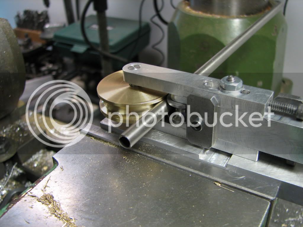
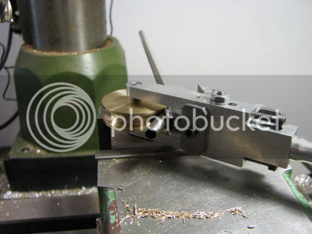
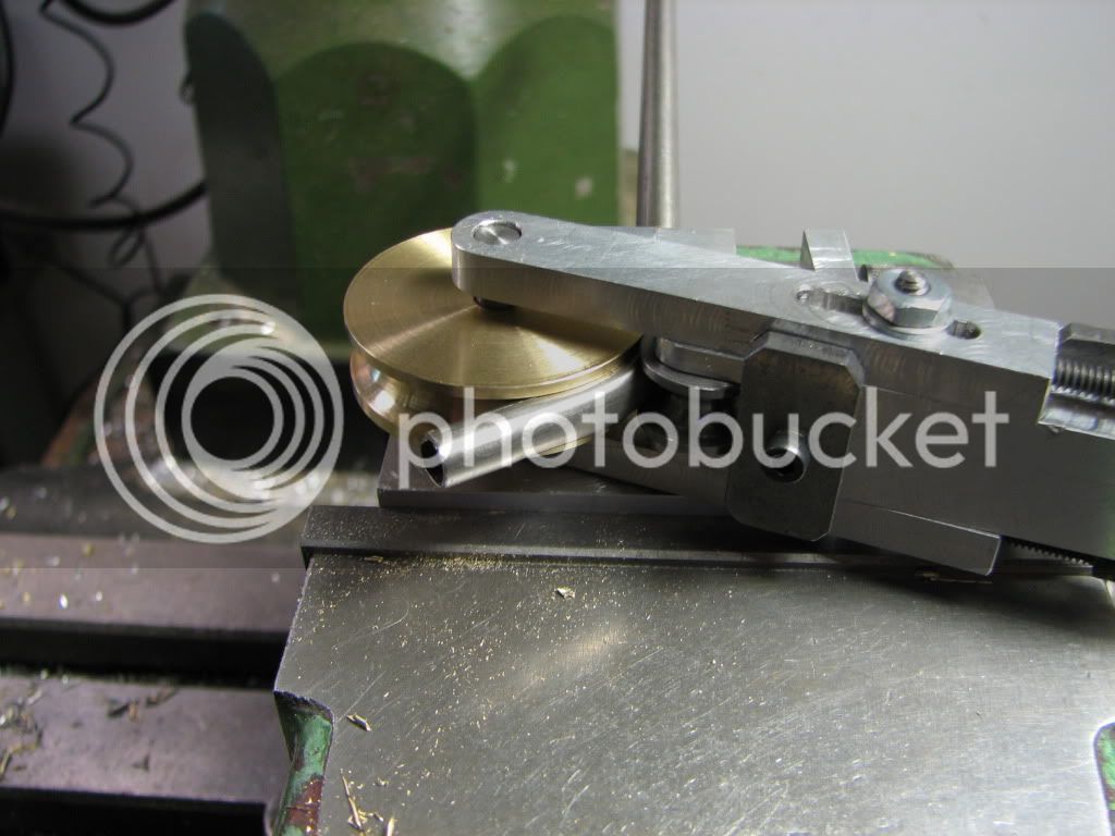
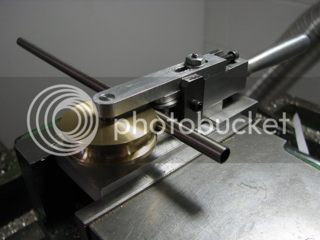
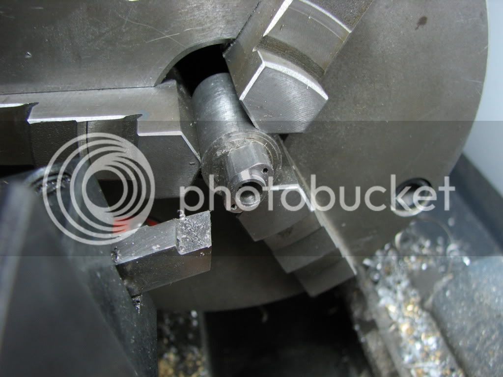
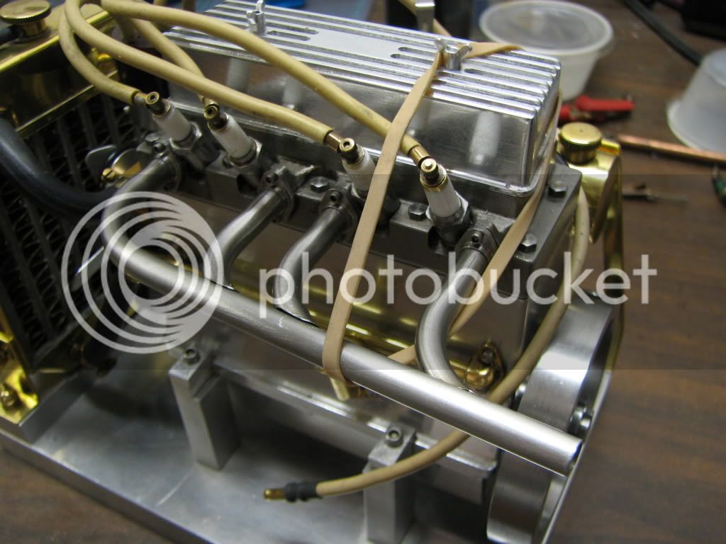
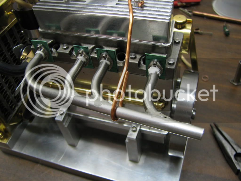
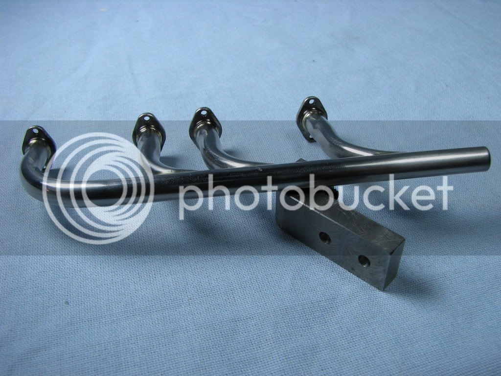
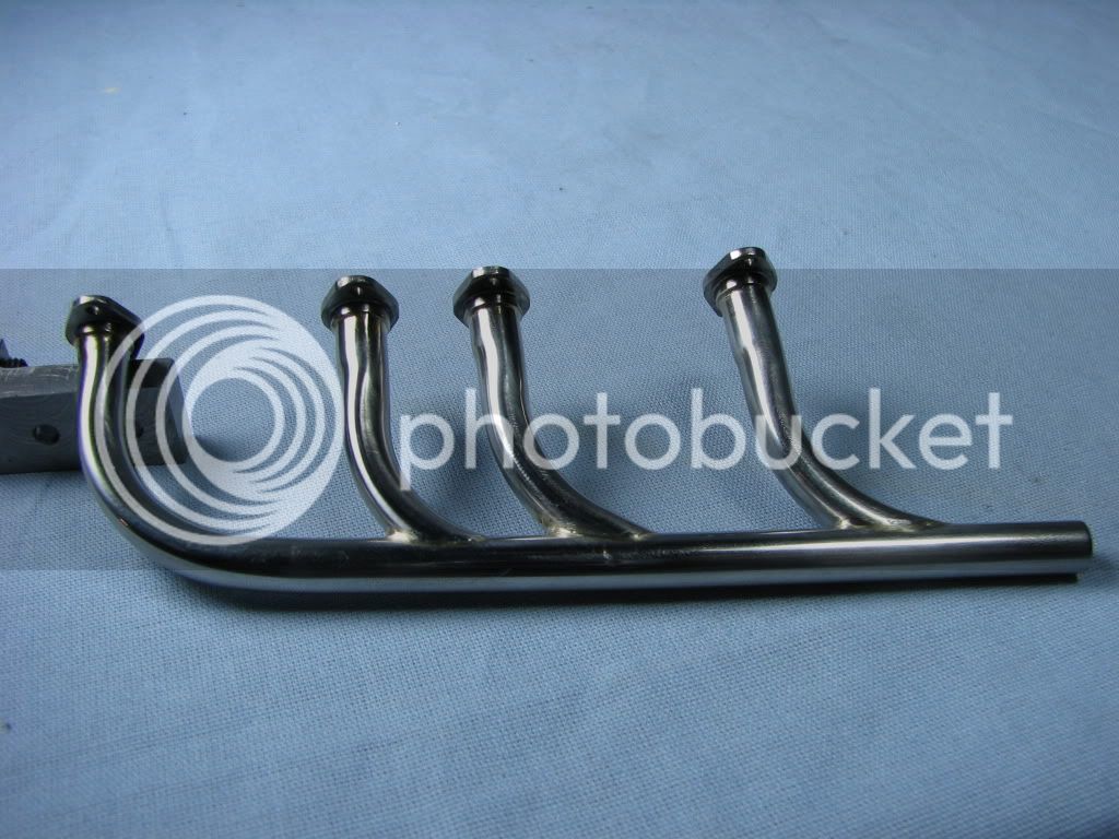
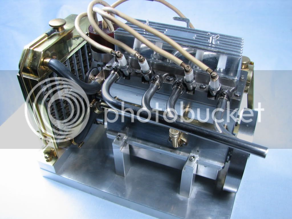
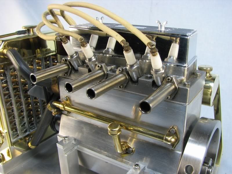
When I first built my 4 cylinder OHV engine I made the simplest exhaust for a few reasons. First, I had tried to bend tubing with automotive type benders and didn't have much luck. Second, I wanted to use stainless steel and trying to bend this material was way more than I had experience for. I have since built a tubing bender for small sized tube and have had fairly good luck but mainly with brass and copper tubing. I ordered some 316 thin walled stainless tubing, .250 OD x .025 wall thickness. This was as close as I could come to my port size although I would have liked a little thicker wall. I think it might have bent smoother but I'll get into that as I go along. The description of the tubing said it could be bent and flared with the 'right' tools. The first set of pictures shows bending the tubing with my small bender. I started out with a 1.00 diameter die but the tubing just wouldn't go around that size so I made a quick new one out of brass. I upped the diameter to 1.50. This seemed to work better although it left a slight flat on the outside. When I removed the tubing from the bender and measured across the bend it was still .253 just like the tubing diameter. I can only surmise that the tubing wasn't soft enough and rather than stretch it just flattened out the outside wall. The inside radius was perfect.
abendtubing.jpg

bbendtubing.jpg

cbendtubing.jpg

dbendtubing.jpg


Next up were the flanges that mount to the head. These started out from a piece of 303 stainless. The stock was progressively drilled out to .25. I knew that I would have to face the pieces after they were cut off so at that time I could take a skim cut to get them out to .253 diameter. The first picture shows the stock turned down far enough to get the required number of flanges plus cutoff thickness and a little more to be safe.
eturnflngstk.jpg


The next shots show the triangular shape being milled on the stock in my dividing head.
fmillflngstk.jpg

gmillflngstk.jpg
 
The dividing head was now rotated up to vertical to do the drilling for the mounting holes. I didn't show the indicating but the part was still true from the horizontal setup. The holes were center drilled and drilled .062 diameter for 0-80 screws.
hstupflngstk.jpg

idrilflngstk.jpg
 
Nice bender, A little off topic but would you mind showing a pic of the other side.
Just curious what your tube stop is.
-B-
 
I only drilled deep enough to do one flange at a time as I didn't trust drilling to deeply and have the drill wander. That would have necessitated starting over so the little extra time was worth it. I don't much like cutting stainless steel even if its 303. The stock was put back in the lathe and the outer hub was cut down to .295 diameter x .062 long. Now the dreaded part, cutting off. On my Logan I have to manually change belts for my speeds so that added another step every time but trying to cut off at the turning rpm just gave me too much chatter. My cut off tool is a 3/8 high speed steel blank ground down to .045 wide and just long enough to part of the piece. The following picture is the hub being cut.
iiflngturn.jpg


Up next are the parts, the main pipe, the individual headers and the flanges.
kflngtub.jpg
 
The main pipe was bent a little less than 90 degrees. I just thought that it would look neater that way. Everyone has their own preferences. I mounted the flanges on the head to hold the pipes while fitting them to the main tube. I first held the individual pipes up to the main pipe and marked them with marker pen leaving them about .04 proud. I then ground a rough notch in them with the bench grinder. To finish the radius I used a smooth rat tail file and a .25 diameter mounted stone in my Dremel grinder. This was the most tedious part, fitting, grinding and more fitting. I had a little wiggle room with the pipe as the total thickness of the flange is .125. After fitting each pipe to the main tubing I then marked the main tube with a fine point marker and ground out the openings about .04 smaller than the marked line.
mpipefit.jpg

lmainpipe.jpg


The next shot shows all the parts held together with a rubber band. A little more grinding and everything fit fairly well. The smaller the gap the easier it will be to silver solder.
npipeassmbl.jpg
 
After I was satisfied with the fits I took a piece of copper wire and bent it up to hold everything in place for soldering. I used the engine itself for the fixture not wanting to spend the time to make up a steel plate with eight 0-80 tapped holes. I removed the spark plugs and made insulator gaskets to keep the heat from transferring to the head. I have a miniature oxy-cetylene torch with some very small tips so my plan was to silver solder the pipes first and then just tack the flanges in place. Once done I would remove the assembly and finish doing the flanges. I must say that at this point everything went as planned. I don't have any pictures of the silver soldering as I didn't have enough hands to perform that task and take pictures. The only picture in this set is everything fluxed up and held together for soldering.
opipeflux.jpg
 
After some judicious filing, remember the metal wall is only .025, with my small jewelers files and varying grades of emery cloth I got down to what you see in these pictures. Somewhere along the line I managed to put a tiny nick in the main pipe. I think I'll fill it with silver solder and then have the whole affair nickle plated this winter.
ppipefinish.jpg

qpipefinish.jpg
 
The last two pictures show the before and after shots. The first being the new header and the second being the old straight pipes. I do think that the new header gives it a more racy look.
rfinishassemble.jpg

4cyl2.jpg


There wasn't much machining in this tutorial but nevertheless I hope that it helped provide some information on fabricating. I have since done numerous searches on tubing benders and I'm going to build another one to see if it will prevent the flat side from forming on the stainless. Maybe not, but I'll never know unless I try. In this case I just think it was the material.
gbritnell
 
That looks really good, the flanges turned out great.
I have trouble parting for some reason, I would have had to make them one at a time.
-B-
 
Lovely job on that GB.

I have a tube bender very similar to yours, and gives exactly the same results. Perfect on brass and copper, but a flat on thin wall stainless.
Personally, I think a bender of the type with a flat shoe might give better results, but because I don't have one, it can't be proven.

Blogs
 
your tutorials are always very interesting gbritnell, thank you for sharing them :bow:


BTW, yes, the engine now has all another look!

 
Great tutorial and excellent pictures also. Thanks for sharing this GB. The engine is a real beauty too !!! :bow: :bow: :bow:
 
GB,
Thanks. Your posts are always clear and helpful.
Gail in NM
 
GB,
Thanks again for a great lesson. You are amazing :bow:
Tony
 
well your new header begs the question, whats it sound like? ;D Video please :eek:
 
hedgehog said:
well your new header begs the question, whats it sound like? ;D Video please :eek:

Hey hedgehog...please tell me your name's not Ron!! :eek: :big:
 
I am invited to a concours car show next Sunday. A modeling car forum for large sized models has a display set up and I will be running some of my engines. I will do a test and tune on Saturday so hopefully there won't be any gremlins on Sunday. I will do a video then and post it ASAP.
gbritnell
 
Hello G!

Did you put the plans for the tube bender in the download area? If not can i get a copy of the drawings? I think i can bend brass tubing now. I was annealing it wrong. Tried it the right way and it bent like warm butter.

Do you use the lead free plumbing solder or something different?

What do you use for flux?

I made a quick set of pipes for the Peewee and used solder for electronics. Now it's time to make a perminent, better quality set of pipes.

 
Back
Top