


Oh no, why have I started another project before i've finished the previous two? Well, it was Jan Ridder's fault again! He recently posted his Micro Stirling Engine on his website - I had to see it so asked for the plans, which he was very kind to send to me. The problem is, I just don't like making stuff from other peoples plans blindly! It never seems to suit my materials or processes so I have to change things - but I probably go too far.
This time I've tried to combine the best ideas from Jan's and another engine I found on youtube - see below:
http://heetgasmodelbouw.ridders.nu/Webpaginas/pagina_stirling_1_euro_10/frameset.htm
[ame]http://www.youtube.com/watch?v=dAV_nWTwWR4[/ame]
Mine is going to end up a little larger than these two mainly to make things a bit easier for myself and what I have to hand, it should also give it a slightly better chance of running.
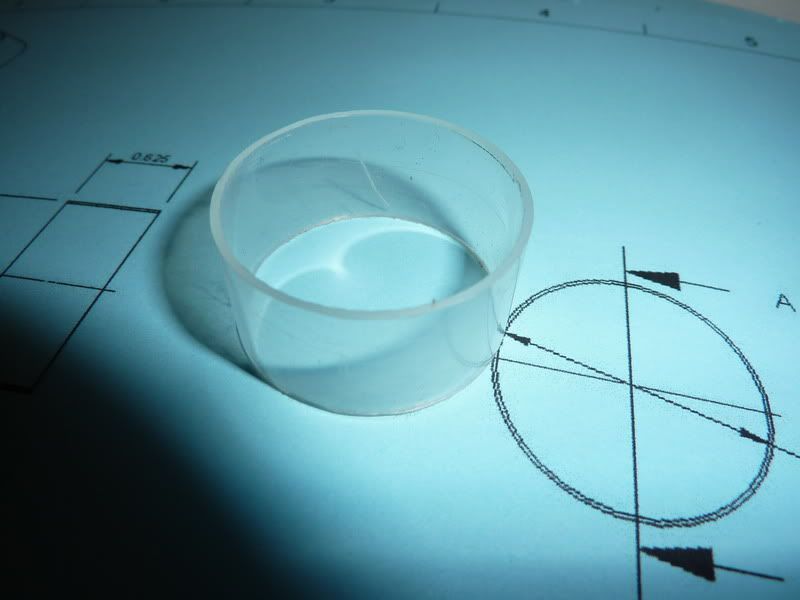
I have done the CAD model which took a bit of working out and have now completed the 2D drawings. I did calculations to ensure the ratio of swept volumes between displacer piston and power piston are almost the same - this is quite important as it largely governs the temperature difference the engine can run on, of course there are a lot of other factors but I think this engine should work.
Please see attachment for the 3D model.
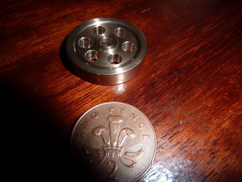
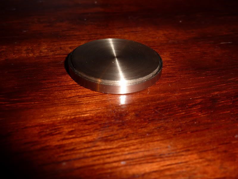
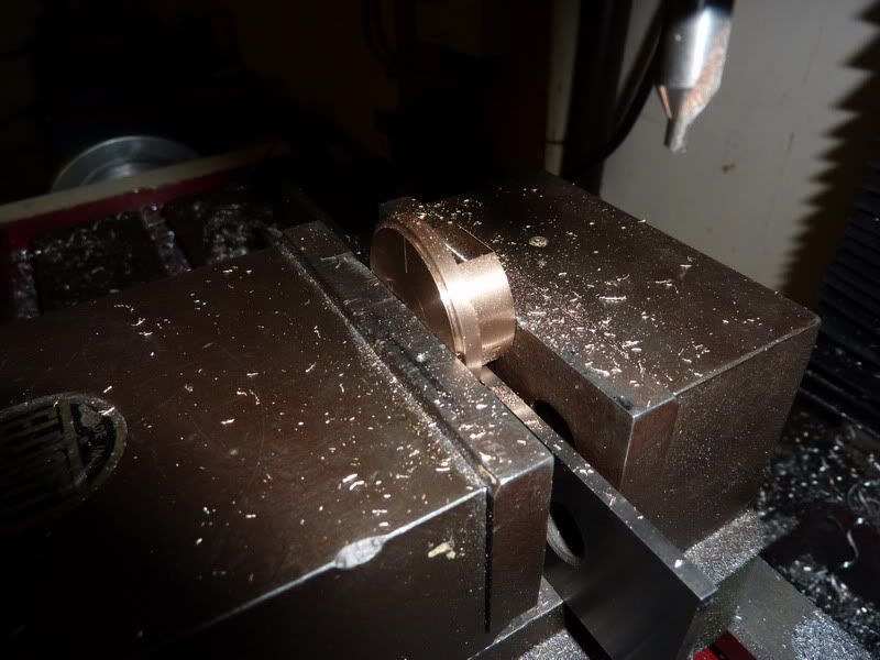
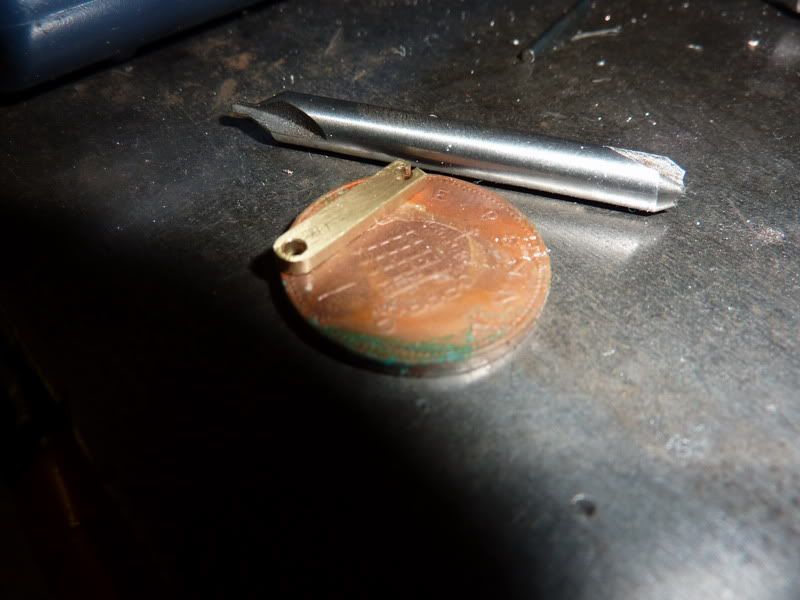
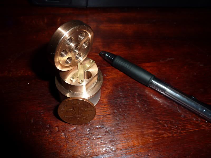
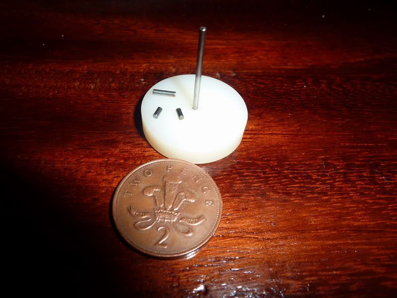
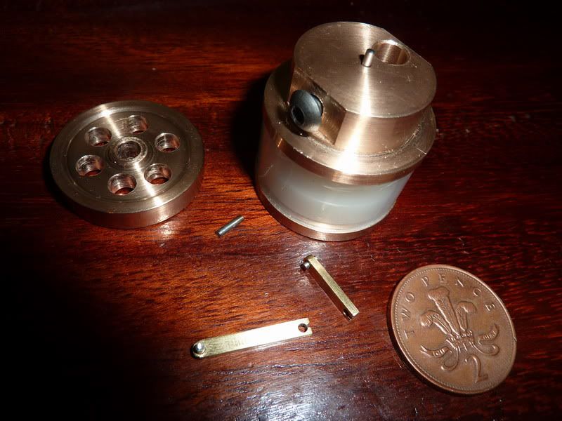
Tonight I started cutting first metal - A slightly frustrating night but it has yielded 1 component - I started off collecting some materials together but then got bored of that so started turning the bottom displacer cover or hot plate as I've called it on my drawings. I quickly realised that because of the thin register I need to turn that and part it off a longer piece of stock. I have some cast gunmetal that I'm using. The slither that I had planned to use has now ended up as the flywheel! This means I've already deviated from my drawings, when I felt the weight of the aluminium I'd planned to use for the flywheel I thought it was too light, so I thought I'd use the cast gunmetal and thicken it up by 1/16" to 1/4" thick. The diameter has ended up as 1.22" or something rather than the 1.5" I had originally planned. Actually, this now seems a bit heavier than I thought so may have to do the ally one after all but maybe keep the 1/4" thickness, then it might be heavy enough.
Anyway, here it is:

The cake is 2nd hand, my 2 year old son licks the icing off but he didn't do a very good job on this one so waste not want not!
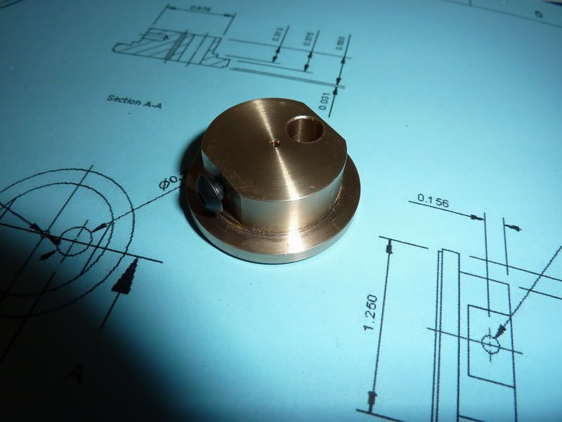
Feel a bit disappointed that that's all I managed in a night but at least it's done. As I said, it deviates from the drawing in size and material. I couldn't be bothered to find / change tools etc either so the recess isn't quite right. I think I will modify the drawing just to widen the alloy flywheel. Unless this one works then I'll change it to brass. The plan is just to loctite it to the crankshaft - just easier for this little engine, it'll have no power so won't come loose.
This is probably the 2nd most complex part on the engine so at least it's a start.
Nick
View attachment Assembly.pdf
This time I've tried to combine the best ideas from Jan's and another engine I found on youtube - see below:
http://heetgasmodelbouw.ridders.nu/Webpaginas/pagina_stirling_1_euro_10/frameset.htm
[ame]http://www.youtube.com/watch?v=dAV_nWTwWR4[/ame]
Mine is going to end up a little larger than these two mainly to make things a bit easier for myself and what I have to hand, it should also give it a slightly better chance of running.
I have done the CAD model which took a bit of working out and have now completed the 2D drawings. I did calculations to ensure the ratio of swept volumes between displacer piston and power piston are almost the same - this is quite important as it largely governs the temperature difference the engine can run on, of course there are a lot of other factors but I think this engine should work.
Please see attachment for the 3D model.
Tonight I started cutting first metal - A slightly frustrating night but it has yielded 1 component - I started off collecting some materials together but then got bored of that so started turning the bottom displacer cover or hot plate as I've called it on my drawings. I quickly realised that because of the thin register I need to turn that and part it off a longer piece of stock. I have some cast gunmetal that I'm using. The slither that I had planned to use has now ended up as the flywheel! This means I've already deviated from my drawings, when I felt the weight of the aluminium I'd planned to use for the flywheel I thought it was too light, so I thought I'd use the cast gunmetal and thicken it up by 1/16" to 1/4" thick. The diameter has ended up as 1.22" or something rather than the 1.5" I had originally planned. Actually, this now seems a bit heavier than I thought so may have to do the ally one after all but maybe keep the 1/4" thickness, then it might be heavy enough.
Anyway, here it is:
The cake is 2nd hand, my 2 year old son licks the icing off but he didn't do a very good job on this one so waste not want not!
Feel a bit disappointed that that's all I managed in a night but at least it's done. As I said, it deviates from the drawing in size and material. I couldn't be bothered to find / change tools etc either so the recess isn't quite right. I think I will modify the drawing just to widen the alloy flywheel. Unless this one works then I'll change it to brass. The plan is just to loctite it to the crankshaft - just easier for this little engine, it'll have no power so won't come loose.
This is probably the 2nd most complex part on the engine so at least it's a start.
Nick
View attachment Assembly.pdf
 but I thought I might be able to balance the assembly by adding weight to one edge of the flywheel? What is building foam? I've got some quite dense foam but it's squdgie stuff, not rigid - will that be any good? Or is it not dense enough, does it hold on to too much air rather than moving the volume from one end to the other?