Okay, I got some more work done the last couple nights. Working on the valves.
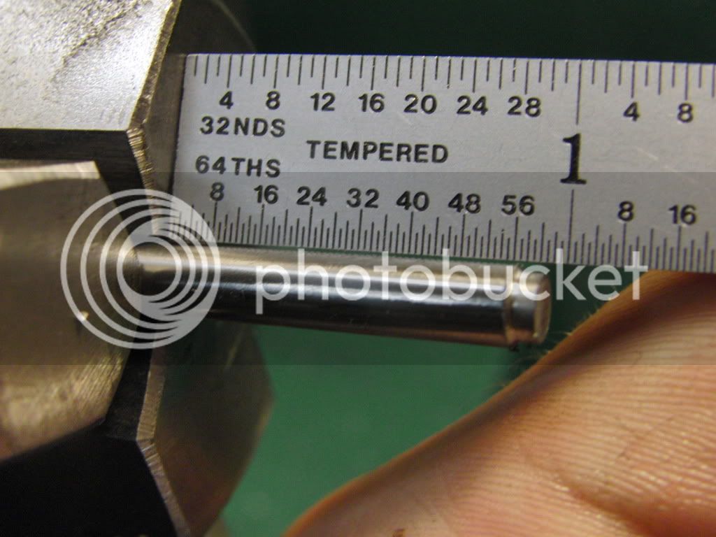
I started With a 3/16" peice of drill rod. I stuck it out past the chuck about 1 inch.
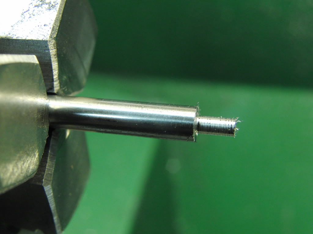
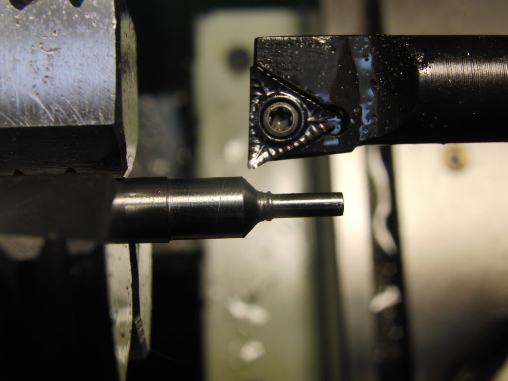
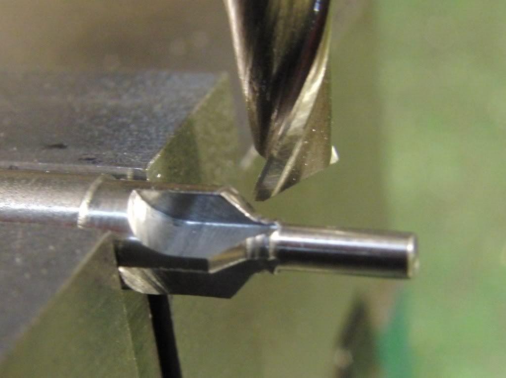
I cut it down to plus .001 in about .2" at a time. I stepped it to decrease deflection.
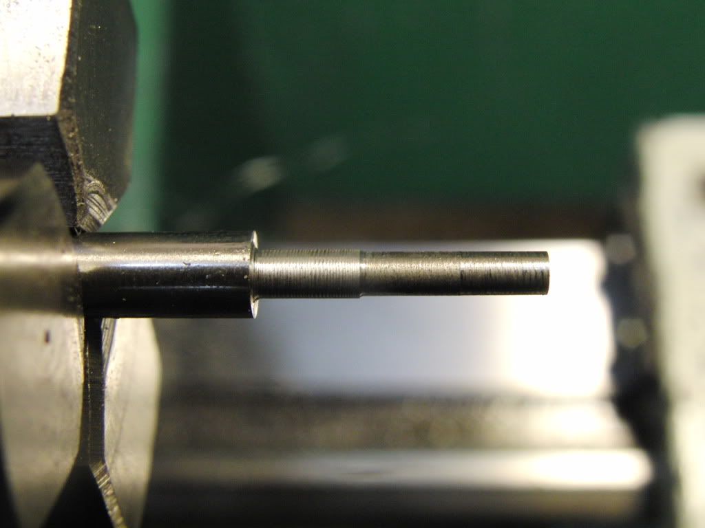
I then stepped down the area above the valve seat to increase air flow.
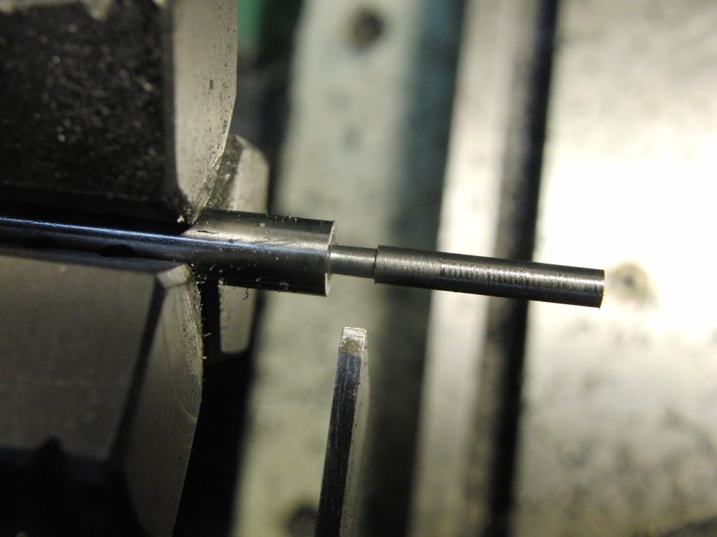
Each valve was finished with 1000 grit, then 1500 grit wet/dry sandpaper. It took me about 12 minutes to get each valve to this point.
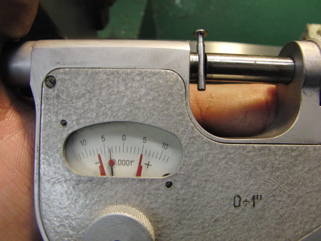
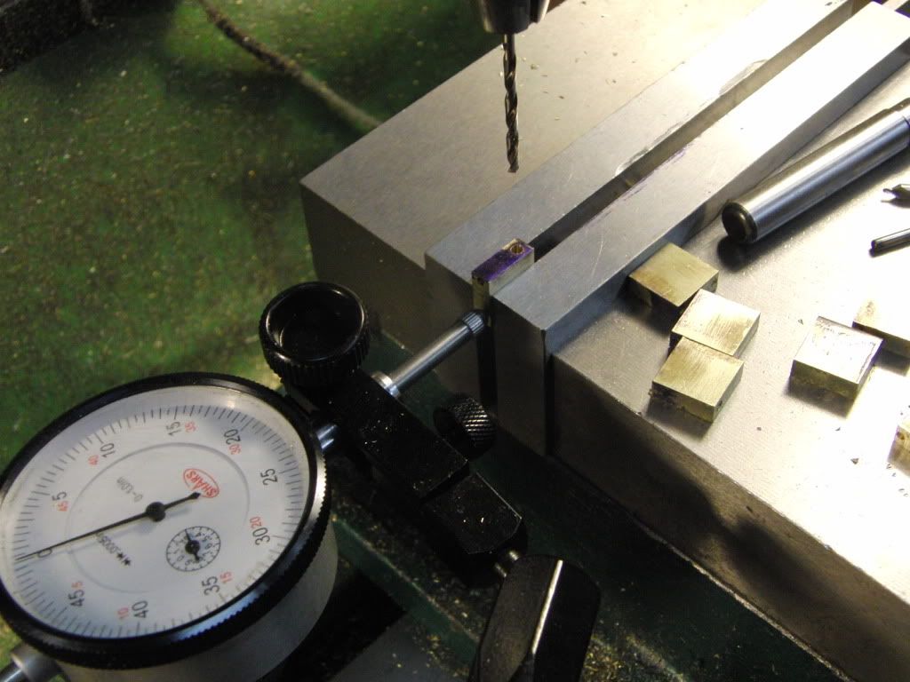
I got this Poland indicating micrometer of Ebay for $30USA. It was a priceless tool to have when making many parts to close tolerances.
I simply cut each valve to the same setting on the dial, then finished with sandpaper and only using the indicating micrometer to measure it. I would highly recommend an indicating micrometer if doing any repetitive procedures.
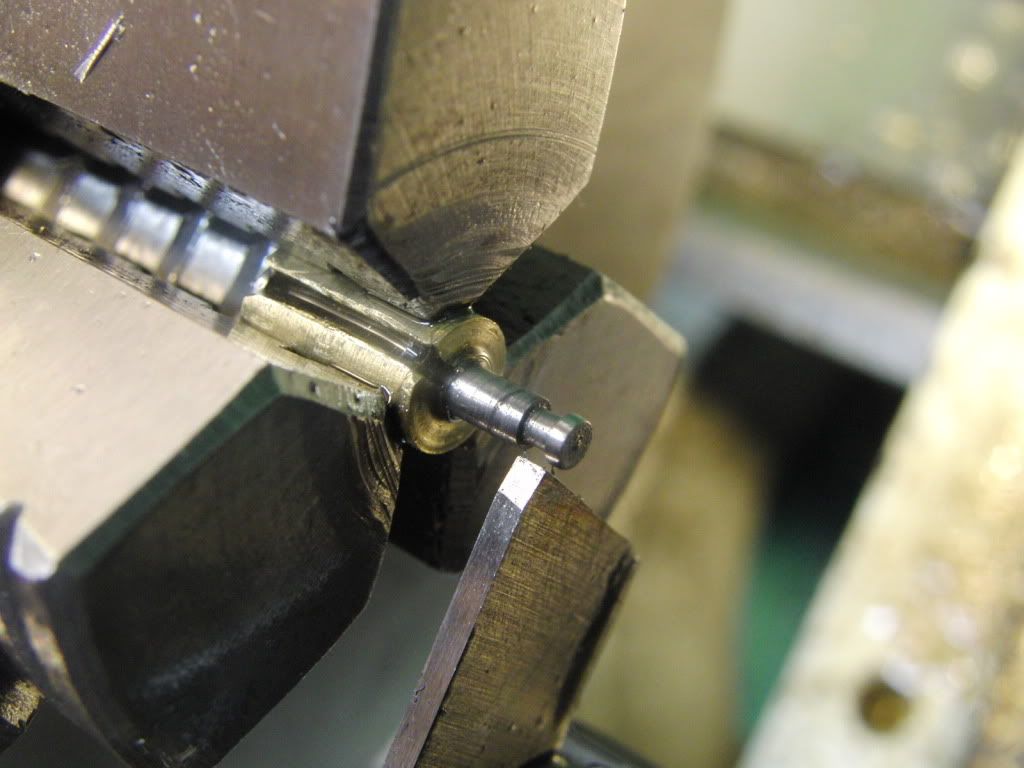
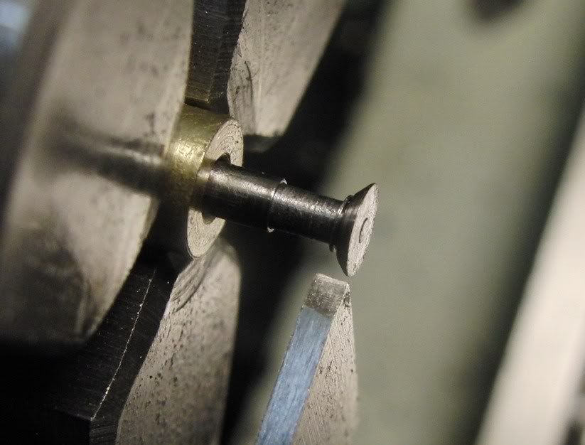
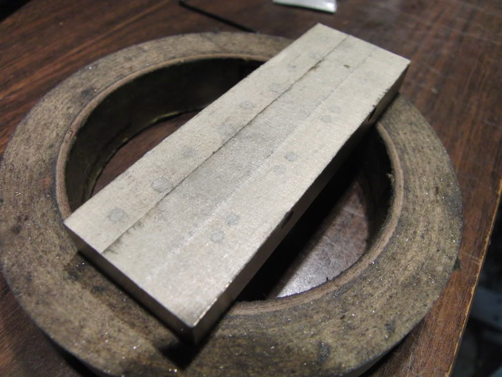
I then made a brass collet to hold the valve.
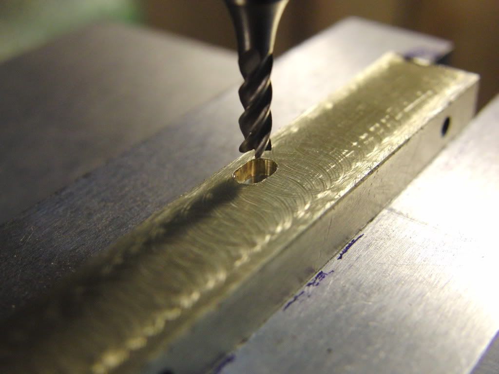
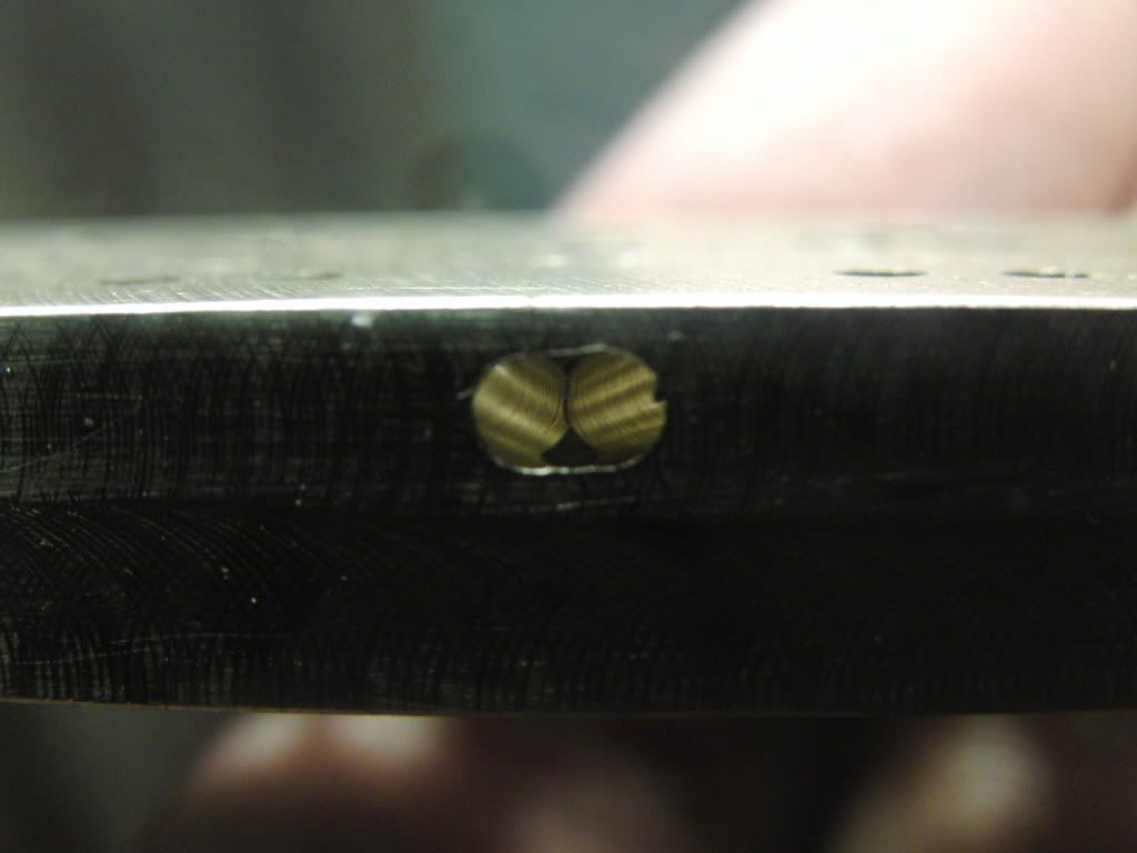
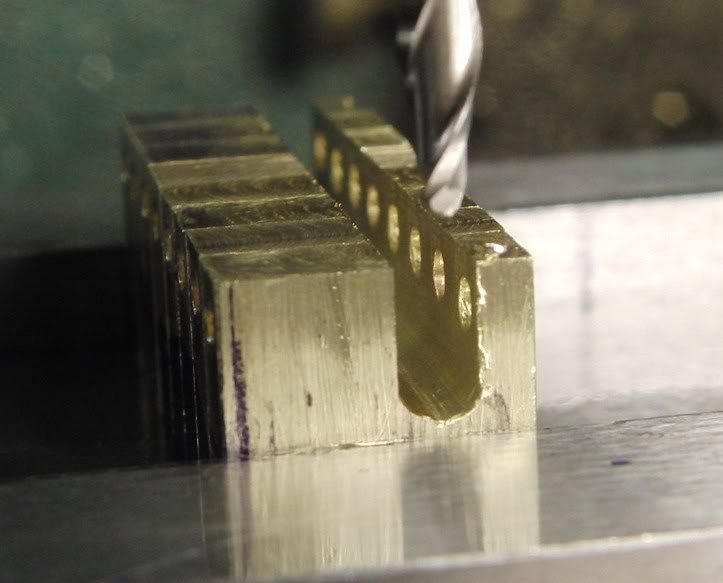
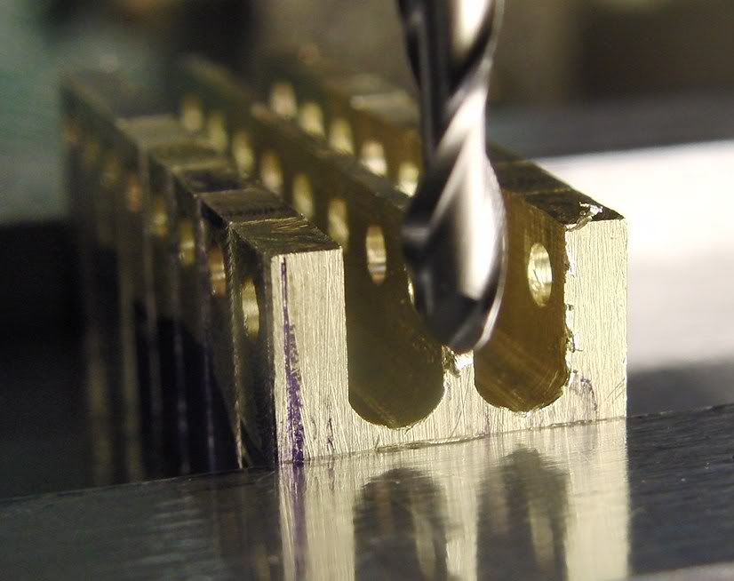
I first cut the keeper slot with a cutoff blade.
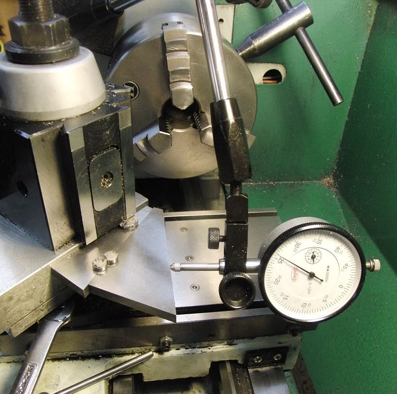
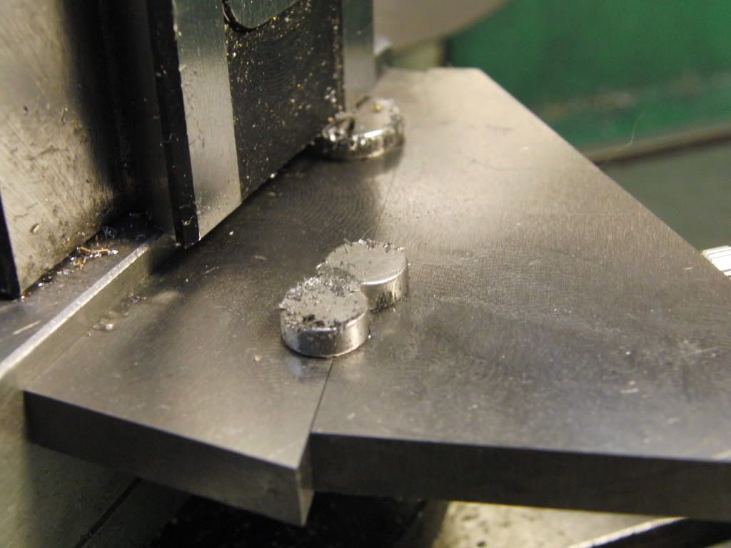
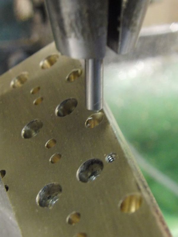
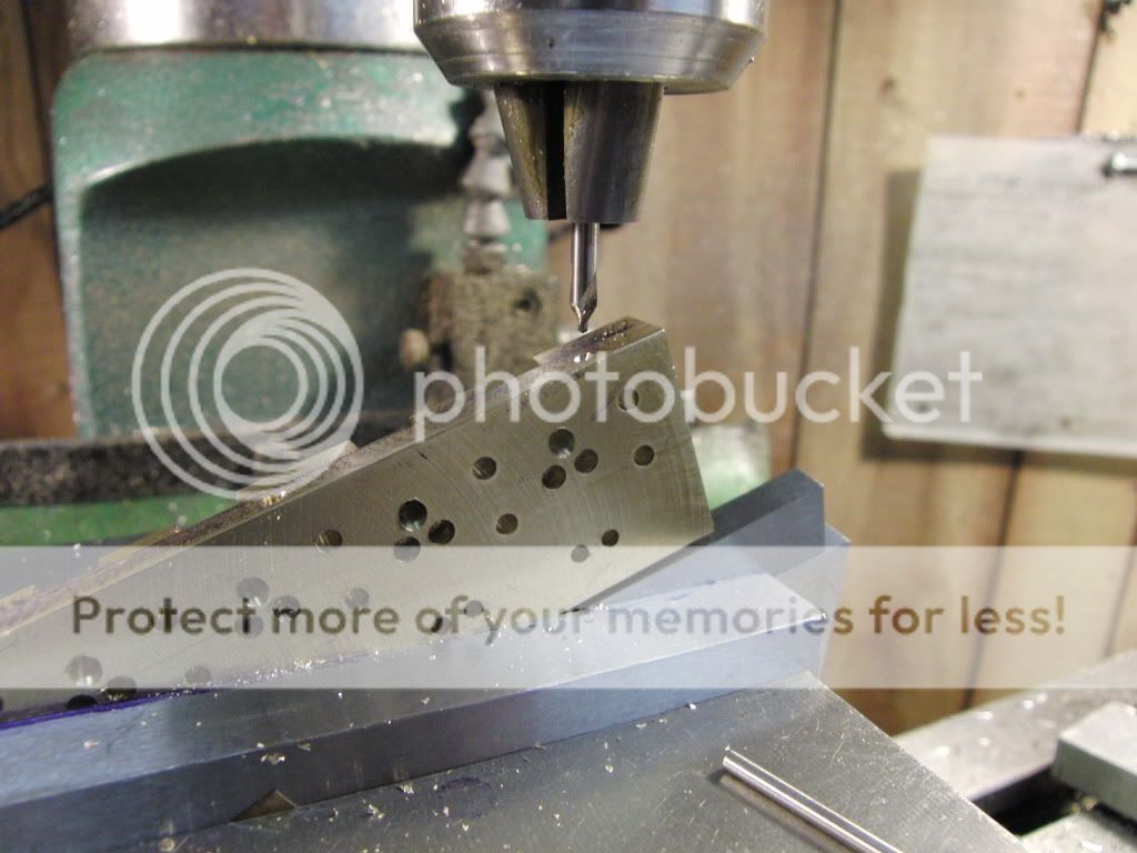
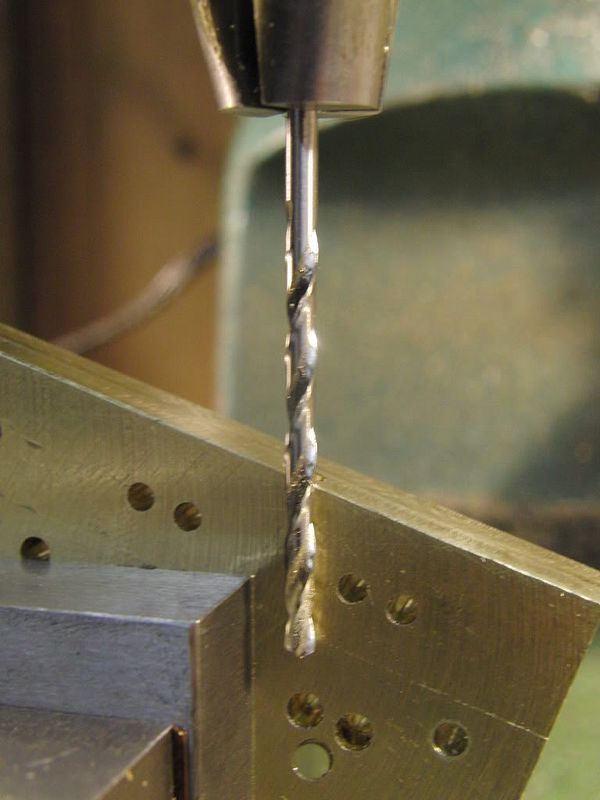
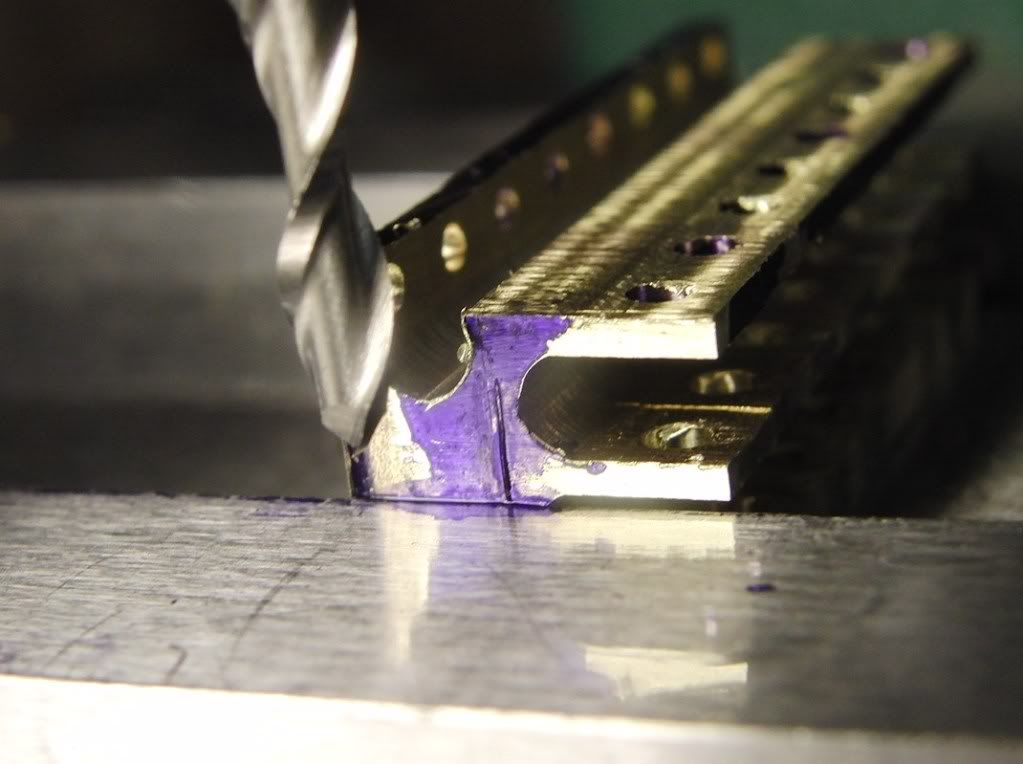
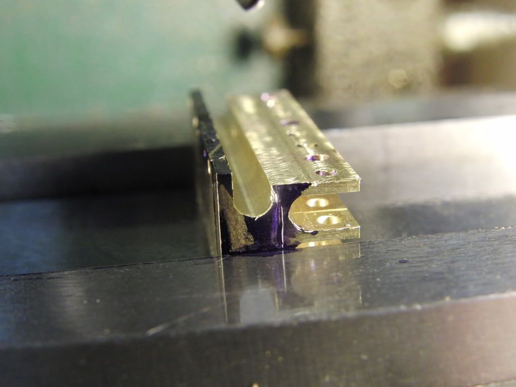
Then I setup the lath to a 45 degree angle using some angle blocks, magnets, and a dial indicator.
I first cut the valve seat cutter blank.
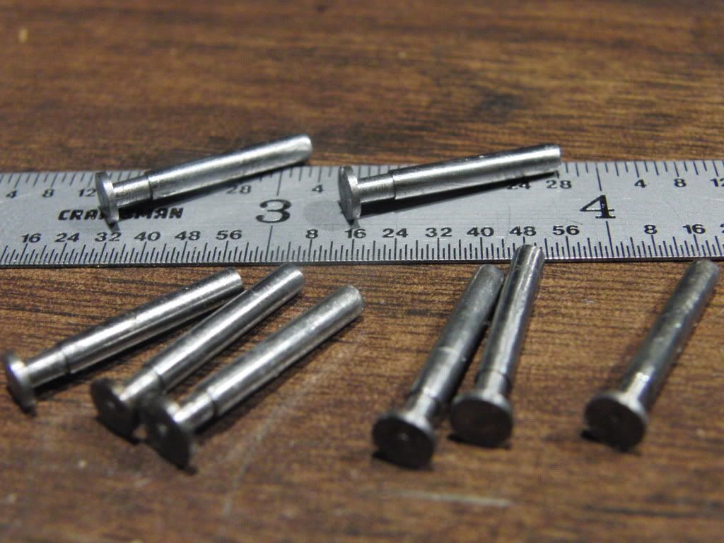
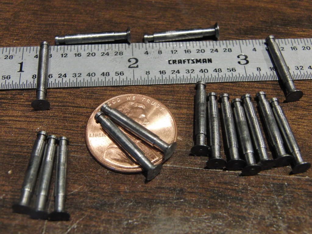
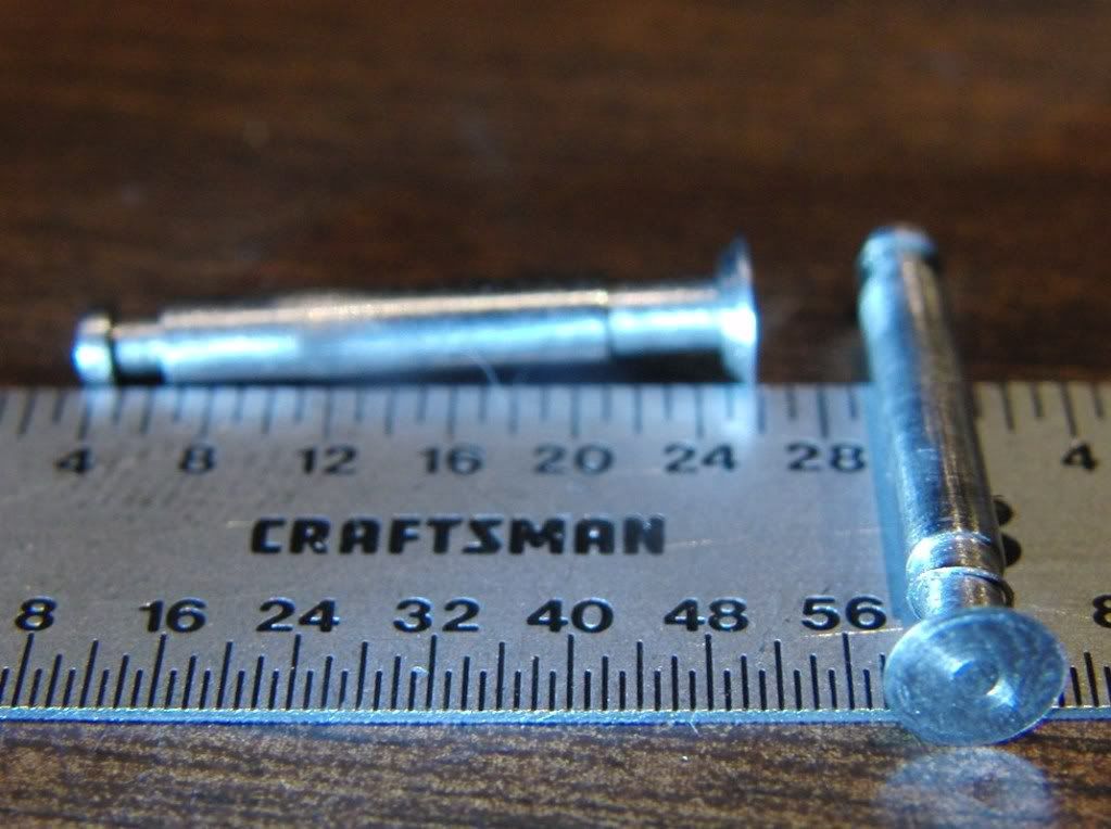
Then the valves.
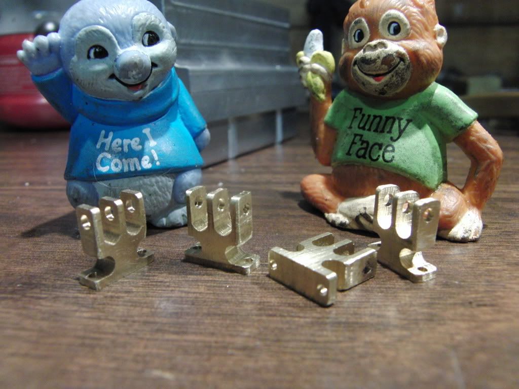
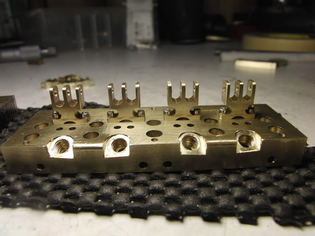
Here they are.
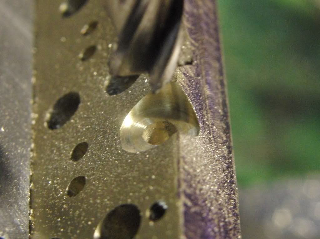
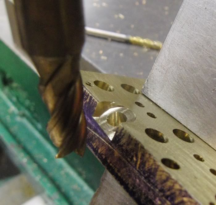
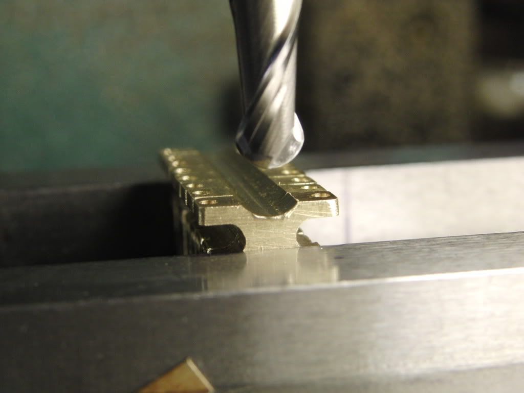
Then I cut the valve seat cutter.
here it is in use.
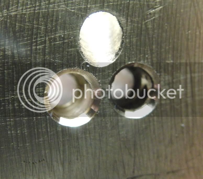
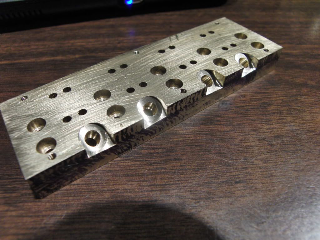
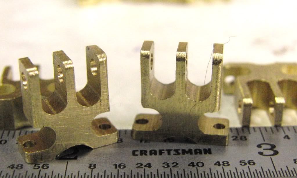
The valve seats.
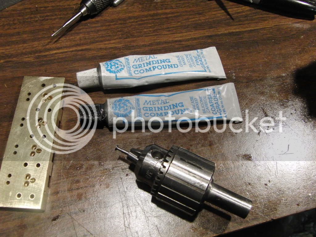
I sill need to lap the valves. I used auto store lapping compund.
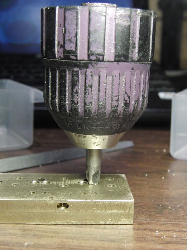
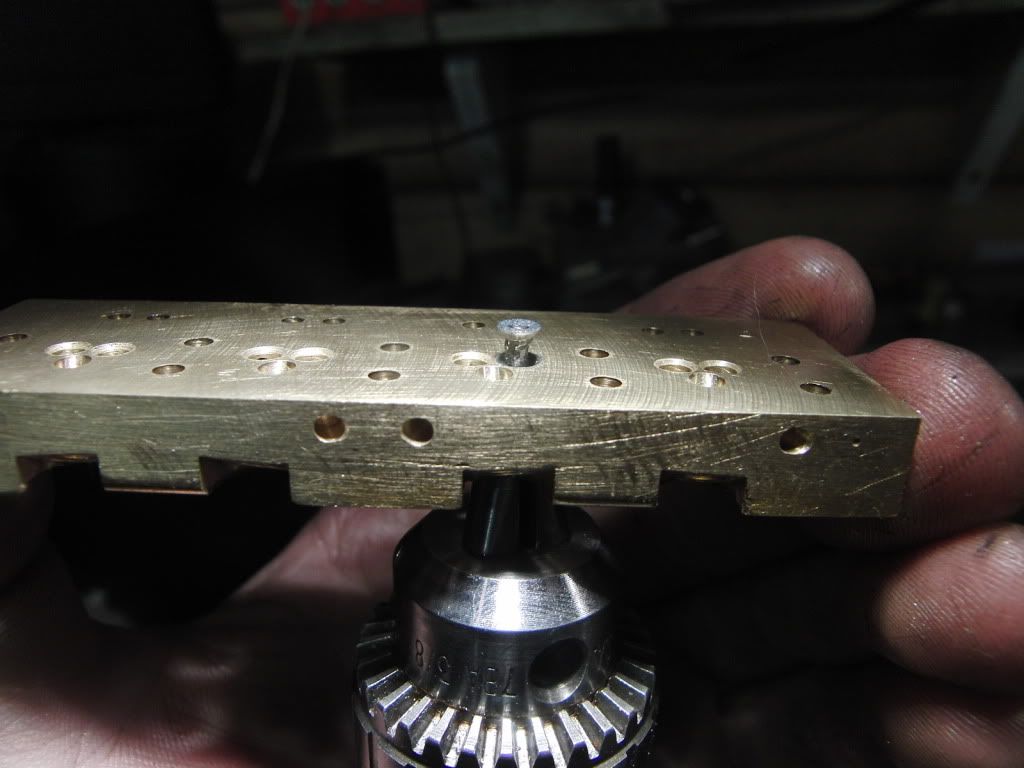
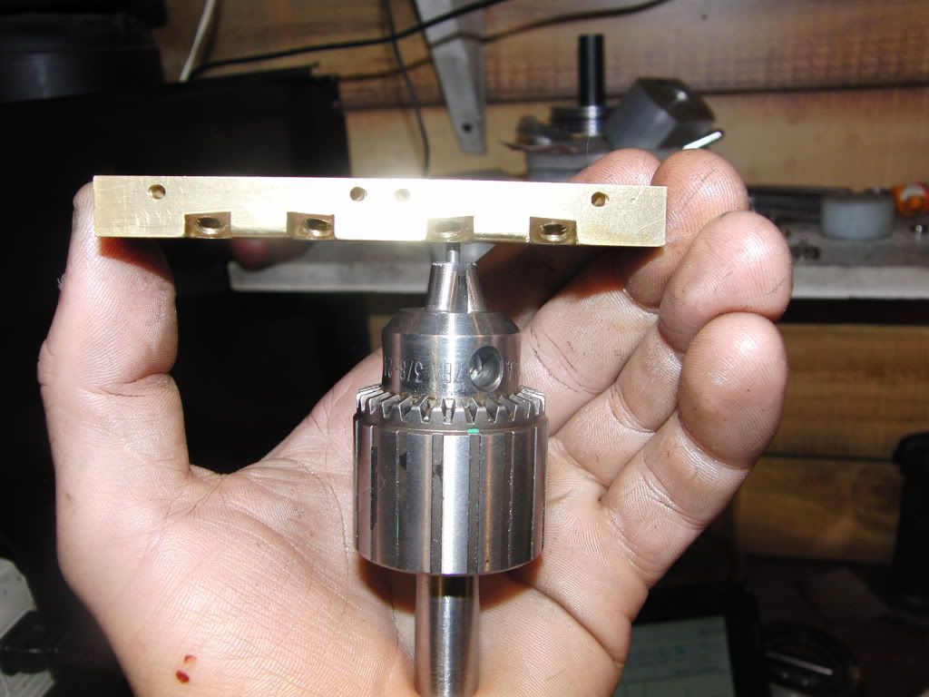
using a drill chuck I held the valve for lapping.
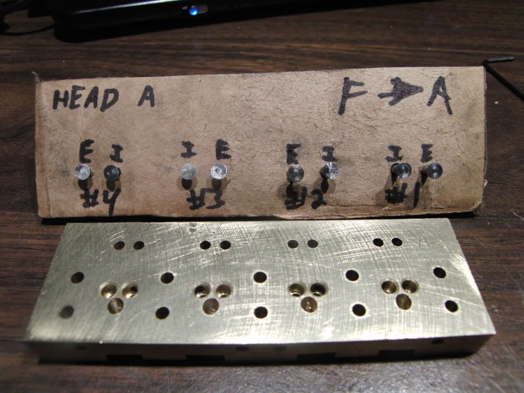
I decided to keep them all in their respective places after lapping.
Then I taped the head to protect the valve seats and head surface.
I used a vacuum gauge to test the valve seat. This is actually testing the valve seat and the valve guide for leaks.
I think this is good enough. You tell Me.
<object width="480" height="385"><param name="movie" value="
http://www.youtube.com/v/AqGOqqePejw?fs=1&hl=en_US"></param><param name="allowFullScreen" value="true"></param><param name="allowscriptaccess" value="always"></param><embed src="
http://www.youtube.com/v/AqGOqqePejw?fs=1&hl=en_US" type="application/x-shockwave-flash" allowscriptaccess="always" allowfullscreen="true" width="480" height="385"></embed></object>
Thats all for now. Time do design the valve rocker arms.
Kel


") Brings back memories.
Brings back memories.