Tiny Inline 4 Cylinder IC

Home Model Engine Machinist Forum

Help Support Home Model Engine Machinist Forum:

This site may earn a commission from merchant affiliate links, including eBay, Amazon, and others.
Hi Kel,

Very nice job on the engine :bow:

To hone the cylinders I use a hone that garage shops use for the small cylinders for the car braking system. They are cheap, in Holland you can buy them at a car part shop for a few Euros. It works really well, if you want I can post a picture of the tool.

Have fun, regards Jeroen
 
Thanks Bob, and Jeroen.

Thus far I have tried to lap them using an alumium bar, but alas all I got was a smaller aluminum bar, and using a needle I can still feel the small ridges made by the reamer. In the past I have used sandpaper on a split wooden mandrel, but in the 3/8" size it is very fiddly and uncooperative, not to mention incredibly difficult to hold on to. The outside of the cylinder liner in only 1/2", I am still healing from the cuts I got whilst holding onto the cylinders. I did not want to use a clamp because I thought this might crush the cylinder slightly and create and elliptical bore, which would make it difficult to machine the pistons ;D . Perhaps I should install he liners and then hone them.

Bob, your talking about the one piece cloths pegs split down the middle? Would I use the split end? I have some maple I could turn down, I assume that the wood would hold the lapping compound well.

Jeroen, I have a brake cylinder hone, but it is much to big to fit the 3/8" bore. I was also thinking about using a ball style hone, they come in much smaller sizes.


Kel
 
Hi Kel,

sorry, missed the 3/8 bore.... brake cylinder hone definitely too big! I agree with Steve, first mount them in the block and then run the reamer through (mounted in the mill). I did a trial on a 4 cylinder block some time ago and just got a good result with reaming when I had it swimming in the lubrication fluid. With too little fluid or non at all it didn't work. Also important to keep the reamer rotating while pulling it slowly back out of the cylinder.

Regards Jeroen
 
Kel,

If you are going to make a holder attached is a suggestion for one:

Clamp.jpg


Apologies for the C-o-C.

Best Regards
Bob
 
Thats a great Idea for a holder Bob. :bow: Simple and effective.

Steve, I will be using the press in first then hone method. I figure I can use the drill press for this. I have just ordered a 240 grit ball style flexi hone. For use on valve stems. I think this will give me a great surface finish, I could not find anything finer. But I'm sure I will get decent results.

I am still designing the water jackets. I have just made a keyway cutter out of some 3/8" drill rod. I will be making a fixture for my Rotary Table to hold the block while I mill out the water jacket. Just a matter of determining where the inlet and outlets should be. this is becoming quite a challenge to design, The water pump is still in my head and not on the computer screen yet, I am not even sure where it is going yet.

My original deadline of Christmas is getting closer and closer, perhaps I was a little too optomistic. But I still got my fingers crossed. The majority of the parts are in the heads of these engines and there are out of the way. Now all I have left is everything else that makes an engine run. :big:

Kel

Kel
 
Anybody else notice Maryak just gave the triple-x world a new idea for an easy-access pair of pants? :big: I only joke! :).
 
BlakeMcKee said:
Anybody else notice Maryak just gave the triple-x world a new idea for an easy-access pair of pants? :big: I only joke! :).

I know you're only saying that because of the leather. ;D

Best Regards
Bob
 
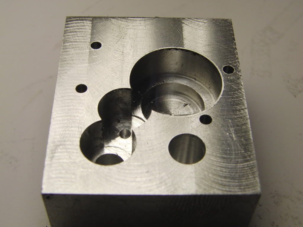
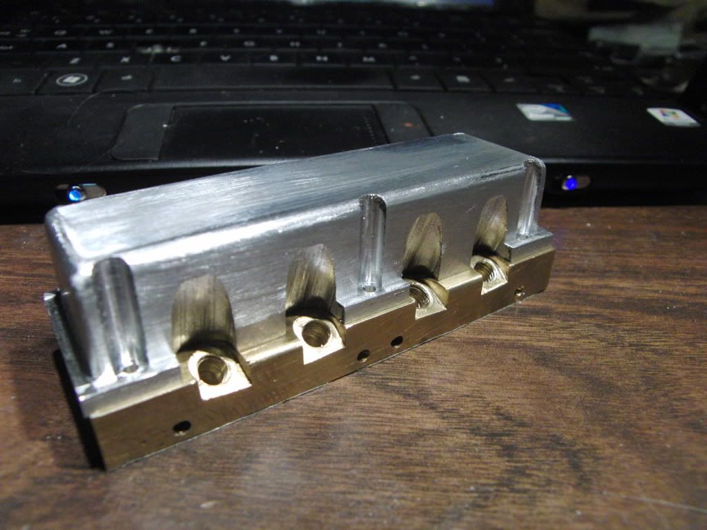
I finally pulled the trigger and started milling the water jackets.

I decided not mill them from the side and instead use Steve's Suggestion of using a key cutter.

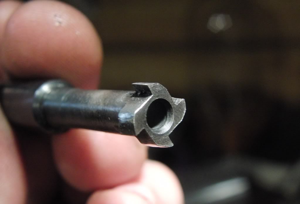
I had to make the key cuter since I did not have one to fit the bore.

It is made from 3/8" drill rod. You can see it below.
CIMG1516.jpg


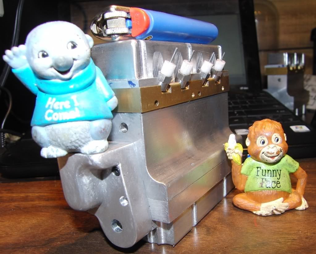
Next was to com up with a quick way to locate each bore on my rotary table.
I made a tooling plate for it awhile ago, so it was a matter of getting the R/T centered to the spindle, then locating each bore.

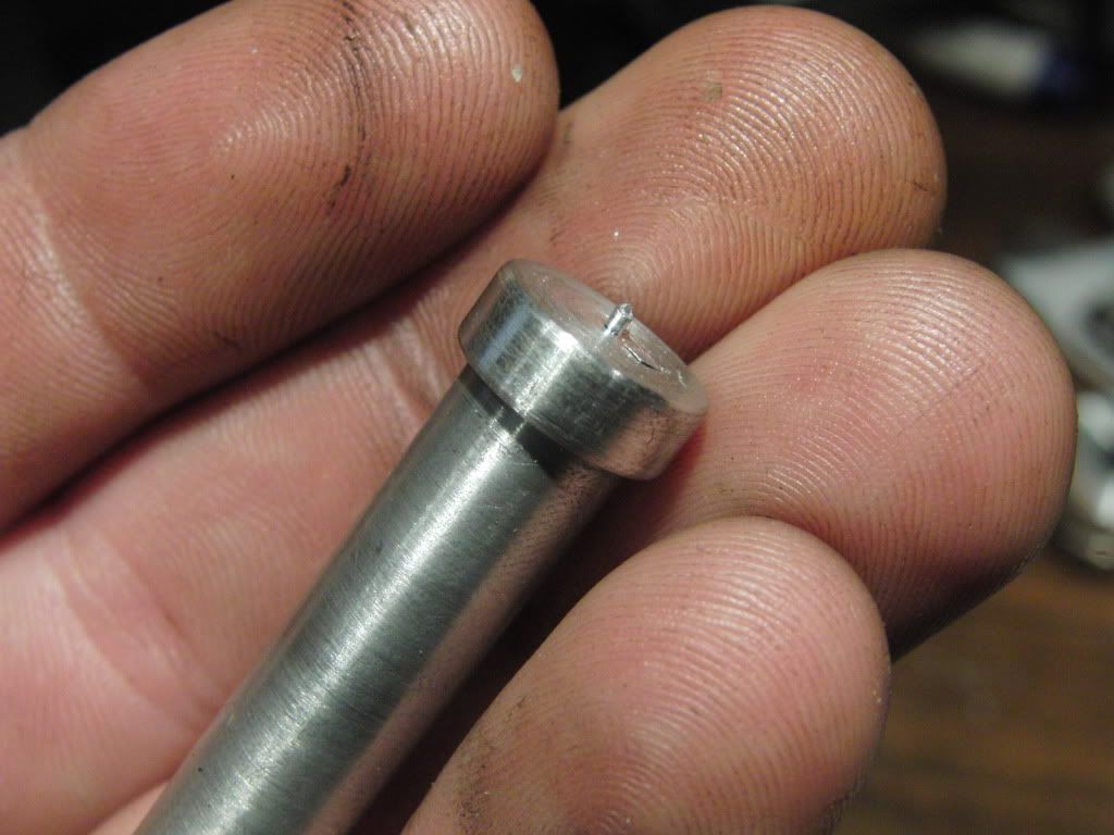
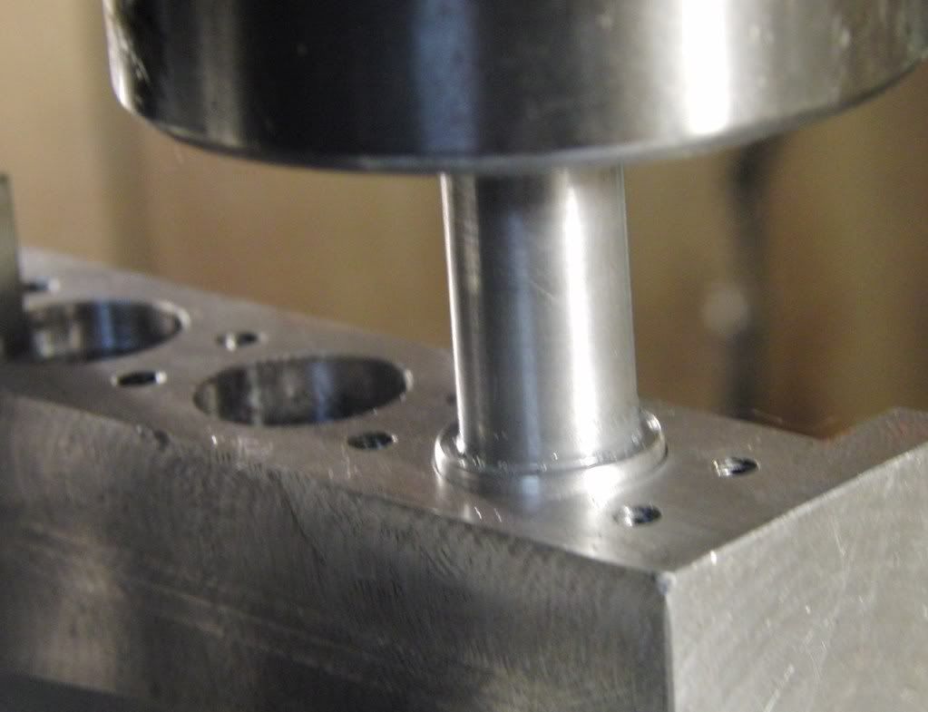
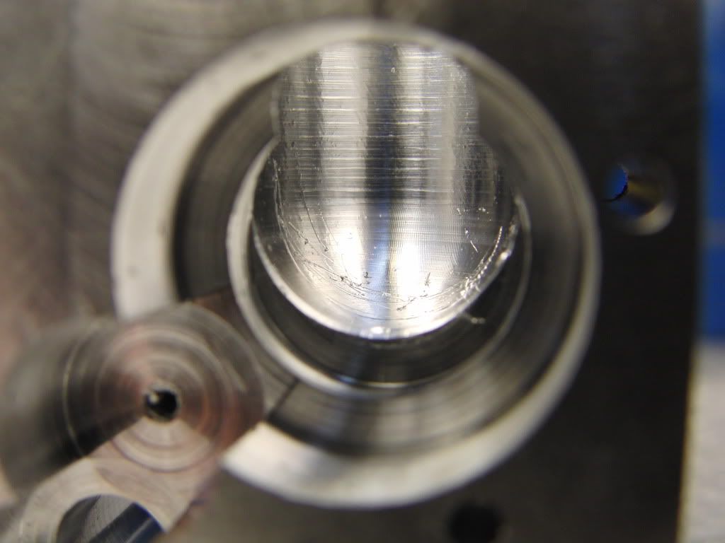
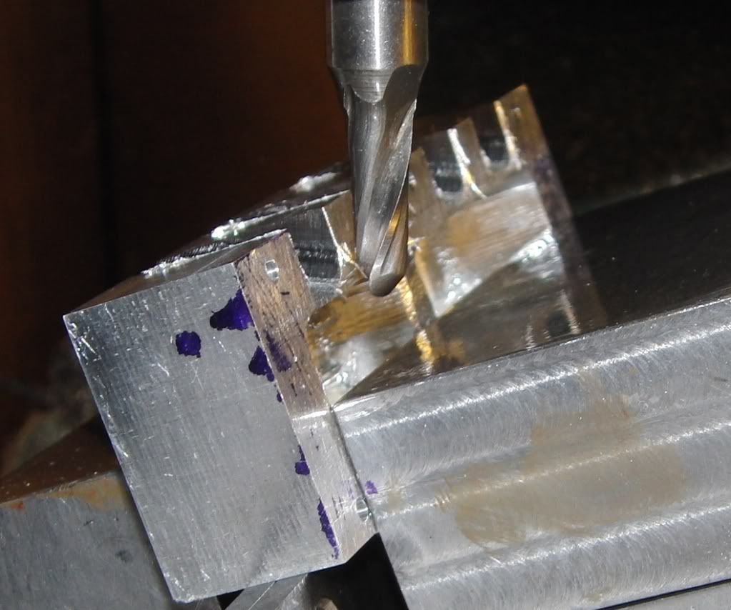
I made a slug out of aluminum with a 3/8" shank and a .5" large end.
CIMG1517.jpg


I stuck that in a collet in the mill and put it in the bore of the first cylinder, while it was still in the bore I then clamped it in place.
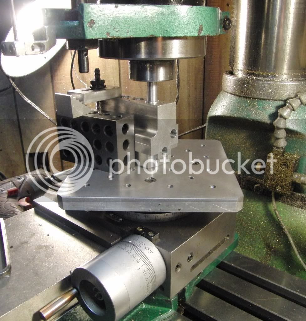
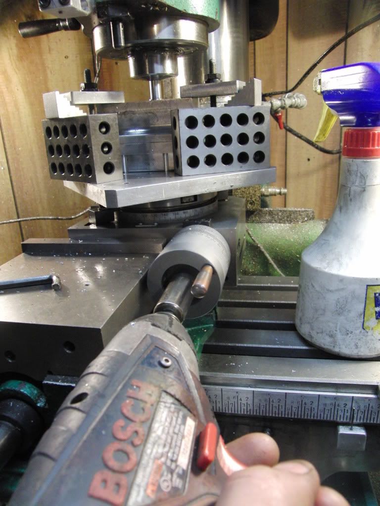
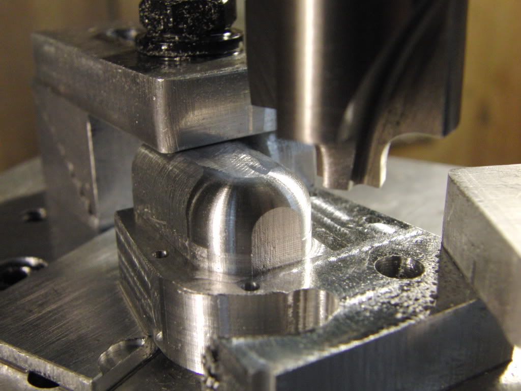
CIMG1518.jpg


Here is the setup.
CIMG1519.jpg


I used a small cordless drill to make turning the rotary table easier. I had to make 4 passes in each cylinder, at 72 cranks per revolution that would be 1152 cranks of that small wheel for each block. (No Thanks) the drill wil be nice.

CIMG1520.jpg


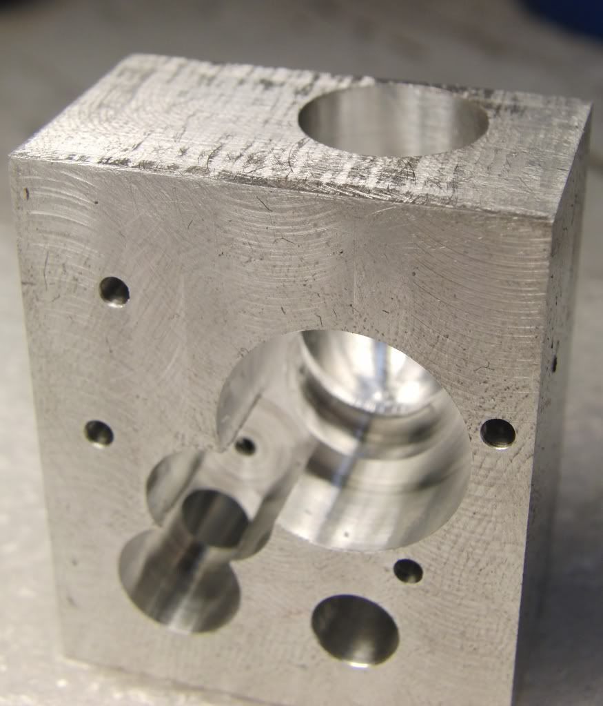
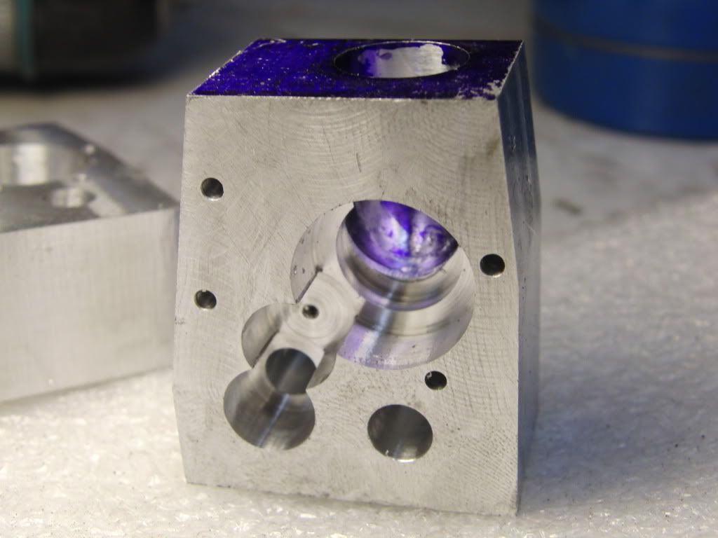
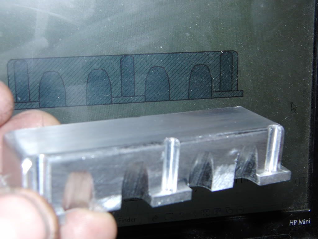
I now need to decide where to Drill the holes.

I was thinking about drilling a hole from the back of the engine at the bottom of the water jacket (This would be the inlet) and then drilling a second hole from the front at the top of the water jacket (This would be the outlet) I was thinking this way the water will flow in from a low spot, travel around all the cylinder liners and then exit at the top, hopefully removing all the air in the process.


Kel


I got the cylinders honed and locktited in place. So that is one more step closer to a finished project.

I also finished designing the timing cover/distributer mount. It was easy to design but hard to decide. There was a lot to think about and I hope I fingured for everything. I suppose well see when I get the rest of the engine designed. For now it is just one (or two ;)) parts at a time.

This piece started like all others, a block milled to final total dimensions. From there it was as simple as drilling a few holes and using end mills to create flat bottomed pockets.

CIMG1665.jpg


Then I drilled a half inch hole for the distributer and finished the bottom with a ball end mill to create a nice rounded pocket for the gears.

CIMG1669.jpg


CIMG1667.jpg


Then I milled the angled sides to the correct length. give or take.

001.jpg


Then the fun began. I milled the front of the cover to expose the tunnel in which the distributer will go.

003.jpg


I then used a corner rounding bit to get a nice radius on the corners.

004.jpg


Then my favorite tool was implemented to get the radius's around the bottom and sides, I also rounded off the bottom of the distributer tunnel.

005.jpg


And the mostly finished part in hand.

006.jpg


Check a couple more parts of the list.

Kel
 
Hi Kel. Your projects looking real good! It takes a lot of hard work, and even more patience to blend milling marks on a complex shape like that.

Great job. :bow:

-MB


It is shaping up nicely Kel. One piece at a time.

I must keep saying that to my self.

Ron
 

Nice work Kel!

Nice job on your little key way cutter too.
 
Really nice work, Kel. I'm sure envious of guys like you, George B and others who turn out such nice shapes in metal!

Chuck
 
Thanks everyone for your compliments. It really means a lot.

I got some more work done today.

Valve covers.

pretty much the same setups as the oil pan, so I will limit my pictures.

Started off by milling out the inside. and rilling the holes.

CIMG1757.jpg


Next up was to make the reliefs for the sparkplugs.

I used a 1/4" ball end mill

CIMG1760.jpg


Pretty boring writeup I know, but this is all basic machining.

here it is with the cad drawing in the background.

CIMG1764.jpg


on the head.

CIMG1767.jpg


and with the rest of the engine.

CIMG1778.jpg


I am not as far behind as I thought I would be, I still have quite a bit to go, but vacation time is nearing, that should give me a few solid days of machine time. That is assuming I can design everything in time.

I am finding that designing the parts is relatively easy, the toughest part is deciding weather or not if that is what I want. I am in a war with myself, I have to think like an engineer and a machinist at the same time. Form or Function, a never ending battle.

Kel
 
Oooo, looking very much like an engine and it's living up to it's name Kel, it is certainly Tiny! Well done :bow:
 
Nice work Kel. It's really starting to take shape. I like the detailing on the rocker cover with the spark plug reliefs. I have reliefs similar to the ones you have for the hold down screws on my 302 v-8 so I made extension bolts with T handle tops for ease of removal.
gbritnell
 
respect to the master
:bow: :bow: :bow: :bow: :bow:

anxious to see how it evolves. Can't wait until the holidays are here ;)

t
 
Thanks Nick, George, and T!!!

George, your 4 cylinder and Steve's V-8 are a constant source of inspiration, you will see that in my distributer design, or should I say, your design :big:

T, I am hardly a master, but I can imitate quite well :big:

Kel
 
Back
Top