This winter's project. A transmission for the 302 engine

Home Model Engine Machinist Forum

Help Support Home Model Engine Machinist Forum:

This site may earn a commission from merchant affiliate links, including eBay, Amazon, and others.
Hi George,

I understand... the geometry of tooth can be machined normally in a lathe, okay ?

Thanks,

Alexandre
 
Here's an update to the transmission. I finished cutting all of the gears. For the spline shafting and collars I had ordered off the shelf stock from SDPI. When I made the cutters for the gears I had made a broach for the splines but it didn't have enough steps to it and was a real bear to press through the stock, and that was brass. I did end up with a very nice spline collar but I was afraid for the amount of bushings I had to cut the broach probably wouldn't have held up, thus the purchase. Luckily when designing the trans the spline stock was close enough to make everything work. The only thing left to do for the gear sets is to broach a .062 key slot into a few of the parts.
First up is some pictures of the internal gear sets. In pictures 2 and 3 you can see the shift collar with the reverse gear moved back and forth.


GEAR SET 1.jpg


GEAR SET 2.jpg


GEAR SET 3.jpg


GEAR SET 7.jpg
 
Looks a lot like the real thing George....Couldn't tell until you see the sid of your hand in the photo!

:bow: :bow:

Dave
 
The next 3 pictures show the gear set for the overdrive. This is located under the tailshaft housing. These gears were 48 pitch so stock cutters were available but I made up a hob for this pitch also. The 2 pitches in the gear box are 36 and 40 so at a quick glance they look pretty close. This set is noticeably different and matches the fineness of the full sized trans gears.
As with the first set of pictures you can see the shift collar has moved from left to right to engage the spline on the gear. The small gear on the mainshaft will be keyed.
George

GEAR SET 4.jpg


GEAR SET 5.jpg


GEAR SET 6.jpg
 
As an addition to this posting I would recommend to anyone wanting to make their own gears to try the hobbing method. The hardest part of the whole job is getting the width of the tip of the lathe tool to size. When I ground the bit I used a magnifier and put the edges of the micrometer tips just onto the bit. I would venture to say I was within a couple of thousands. There is a fellow on Youtube who does a 7 video set on making hobs. As can be seen in the in the following pictures the involute curve is generated quite nicely. This is the reverse idler gear. It is 36 pitch and hasn't been cleaned up yet.
George

GEAR SET 8.jpg


GEAR SET 9.jpg
 
George.
This is work of a real craftsman.
Thank you for showing. BTW: if I could ask, what steel quality are you making the gears and hobs out of?

Best Regards
CS
 
Thanks for the update George. Just gets more amazing as well as more mesmerizing by the day!!

Bill
 
Hi CS,
Knowing that it's not good to run two pieces of the same metal together (wear) I was going to make the countershaft from brass and the mainshaft gears from 12L14. After giving it a lot of thought I decided that although it might help the wear issue it just wouldn't look right and just how much use/wear is this thing going to get. I decided to go with just 12L for everything.
The hobs were made from W-1 drill rod and my past experience has shown that once hardened they are capable of cutting drill rod. If I ever find that different metals are needed I can always make replacement parts.
The spline and spline bushing stock are some type of steel. They say in the listing that it's CRS but although it cuts tougher than 12L it's not as bad as the run-of-the-mill CRS. (1018)
George
 
George, I know this has been said over and over again, but your workmanship is truly a pleasure to see. Thank you for sharing your talent and skills with all of us. Larry
 
Hallo George

You are doing a really fine job with this transmission! It is always a pleasure to have a look at your construction progress.

I also have experimented with this sort of gear cutters some time ago. And as you already mentioned, controlling the profile dimension (especially the tip width) when grinding the grooving tool is the most critical part of the whole gear cutter making.

Having no suitable measuring instruments for such small profiles as well (like a projection microscope ore something similar) I choose another way to generate the fitting tooth shape.

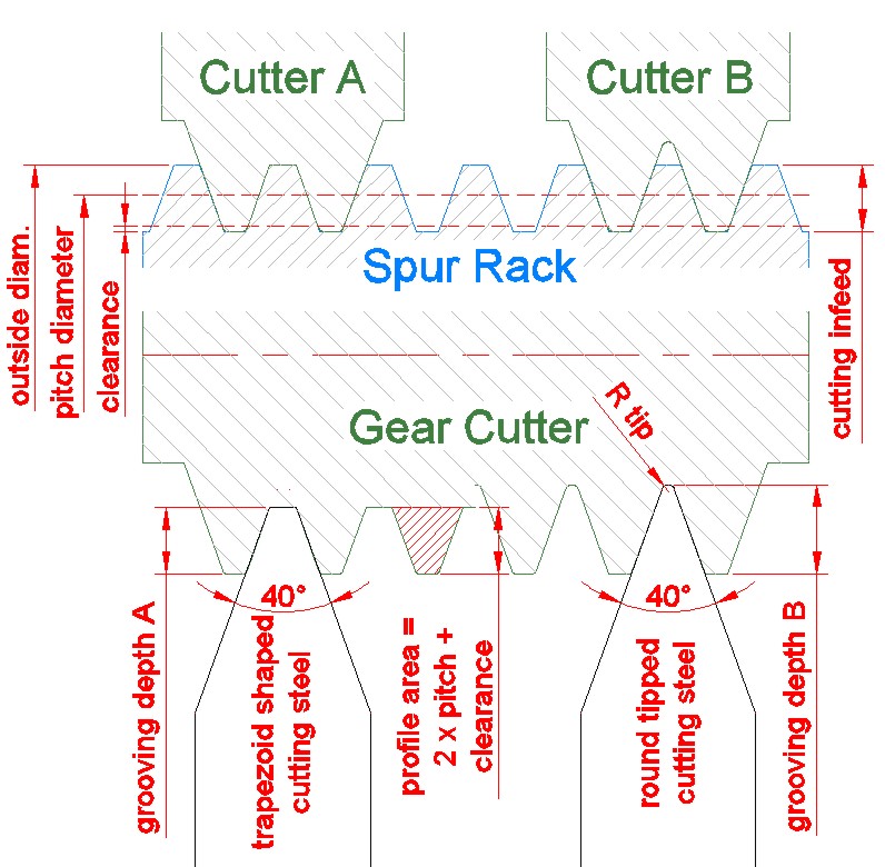
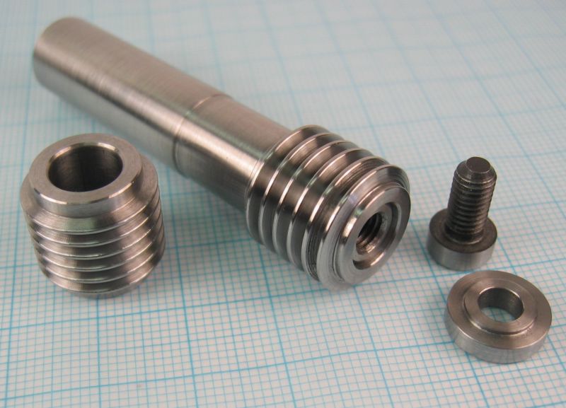
I assume that we always will manufacture the outer diameter of our spur gears by turning the blanks to the desired size on the lathe first. In that case the gear cutter has to cut only the side flanks and the tooth ground. That means the working depth of our lathe grooving tool can be deeper than the pure trapezoid shape of the tooth. Okay, I guess some pictures will be a good idea for easier explanation:


Gear-Hobber-mxx-72.JPG


Grooving tool No.A will generate the needed shape, but you have to grind a dimensionally perfect fitting trapeze. Otherwise you have no real control over the right cutting depth and (much worse) the tooth profile is not complete or too deep.

I grinded the groove cutter (B) with a complete V, very similar to a threading tool but with a 40deg angle. The theoretical cutting depth can be calculated or defined with the help of your CAD system very easily. But we need a small radius at the tip (ore something like that), otherwise the tool would be little durable. As I can’t define this radius precisely enough with my equipment either, a slight uncertainty in relation to the needed working depth will still remain.

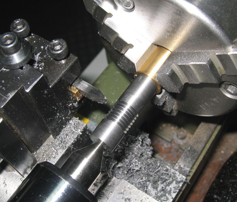
So, depending on the radius, I groove a little bit less deeper then theoretical value, then I measure the actual flanks diameter with the help of two small wires, a principle very similar to thread measuring.


Gear-Hobber-mxx-71.JPG


Being lazy with calculations I transfer this measure into my CAD system and get the new value of the still needed extra depth which can be used in total for all the remaining grooves in the row as well. Special wires are not required, the only thing you have to ensure is a tangential contact to the side walls of the profile. The wire diameter can be chosen in a suitable range, I normally use small drills for this operation.

One additional advantage of this method is you don’t need a new tool for every pitch, one lathe tool can create several gear cutters in a wide range of pitches.

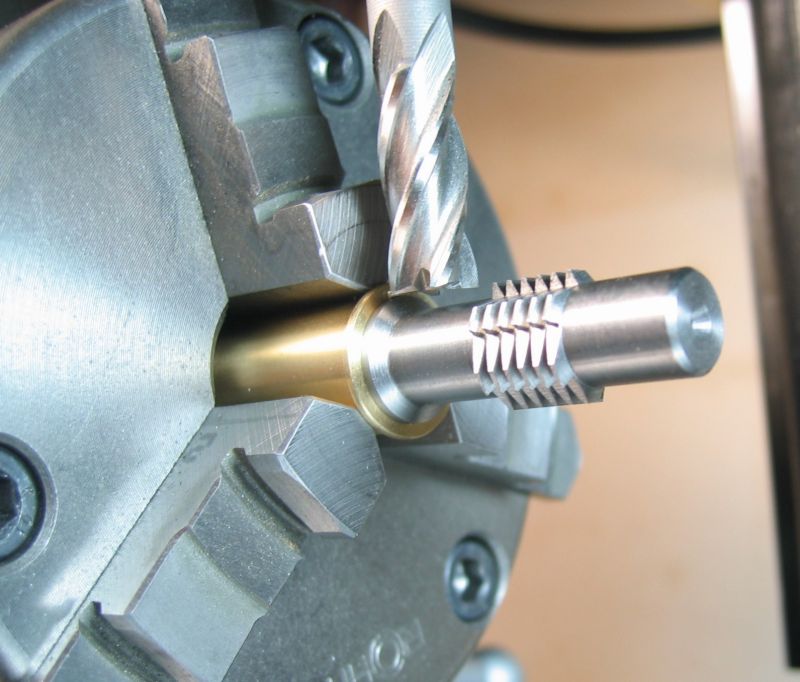
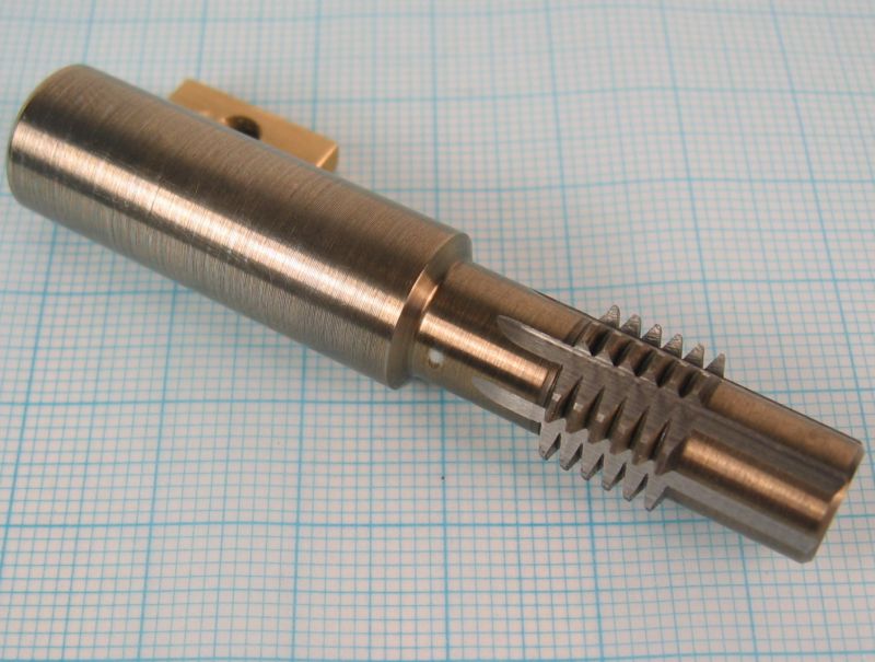
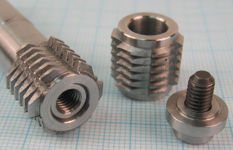
The gear hobs look mainly the same like yours, only the V shape is a little deeper.


Gear-Hobber-m05-01.jpg


Gear-Hobber-m05-04.jpg


Gear-Hobber-m05-08.jpg


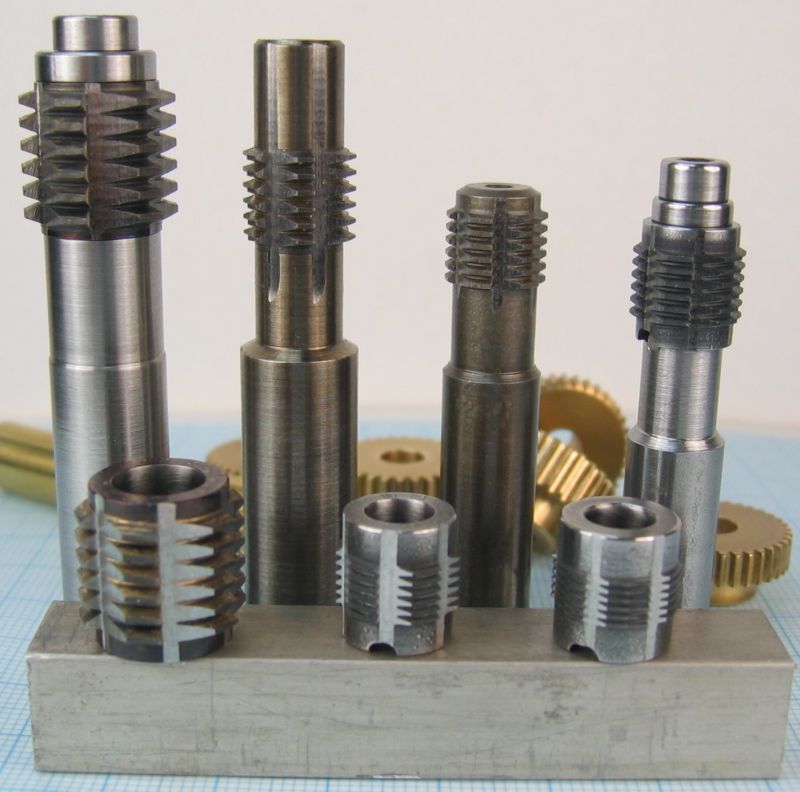
And a little variation, for the second generation I made single cutting inserts that will fit on a small tool shaft. This seems to have some advantages for me, especially for hardening the tools as the small inserts don’t tend to warp as much as a complete cutter.


Gear-Hobber-mxx-02.jpg


Gear-Hobber-mxx-04.jpg


Gear-Hobber-mxx-16.jpg


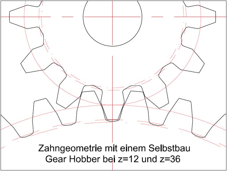
I have made a couple of gears with the tools and the gears work really well for most of our jobs. But for all the readers who are not familiar with this subject, it’s not a real hob process and therefore the flanks don’t get an involute shape. They are only straight formed with a kink beneath the pitch circle. So don’t be disappointed if you start making your own cutters…..ha ha ha…..

This CAD animation will give you an idea of the generated tooth shape using gears with 12 and 36 teeth:


Gear-Hobber-mxx-63.JPG


Achim
 
Achim,
If you made the hob like a worm, inclined the milling head to the helix angle and allowed the (pre-gashed) gear to freewheel - would you not then generate a true volute as in a proper hobbing operation.

Just curious as to your opinion - I have done this for a worm gear in Tuffnol - but that's not the same thing - just a plunge to depth.

Or am I just likely to get a "drunken" gear ?

Regards,
Ken
 
Hi Achim,
Thanks for the wonderful explanation and pictures showing how the hobs are formed. You're correct on the shape of the tooth for gears with small numbers of teeth but all in all I still think it's the easiest way to make gears for home use.
If someone needed a small gear that required a much smoother involute they could make their first complete pass around the blank and then rotate the blank by 1 or 2 holes in the dividing plate and offset the cutter in Z and make another pass, both above and below the original starting point. This would then smooth out the sharp corner on the tooth profile.
George
 
George, it was a pleasure to see you and your transmission at NAMES. It looks even better in person!

RE: Joachim and youself mentioned how hard it is to measure the proper form tool depth for making the cutter. I ran into this problem myself, and realized that the depth wasnt critical as Achim said. I didnt add any radius and it eventually made its own when it snapped off. :( Later on, while rereading an article from several years earlier, I rediscovered Ron Chernich had devised an elegant solution to that problem. He made a tool that he could measure, to make a tool he couldnt measure. You can read about it here. http://www.modelenginenews.org/feeney/pg2.html

Of course, its madness, to make a tool, to measure a tool, to be used making another tool, to finally make a part, to make a miniature model of something else in the first place. But thats why were all here. :)
 
George, you have had your hands inside transmissions before! Your knowledge shows....

Here's how I make my gears and hobs, just for some info... The hobs are made very similar to yours except that they are made in a helix as Ken mentioned. The blank is presented to the hob at the angle of the hob helix angle then is geared to the hob for the number of teeth. I built this from a set of castings from "Power Model Supply" where I used to purchase many, many items.....such a terrible loss....

A photo or two is always good....

Hpim0066.jpg


Hpim0067.jpg


Hpim0068.jpg
 
Bill,
You take your video then open a free account on Youtube if you don't already have one. Load your video. It will ask you to fill in some information about the video, description, category etc. Once loaded open the video and there will be a box below it that says 'share'. Click on that box and copy and paste the link into your message. It's not hard at all.
gbritnell
 
It's been awhile since I posted on the transmission. I have completed some small bits and pieces but thought a tutorial would be in order.
This will be on the construction of the shifting quadrant. This part pivots on a stud on the inside of the case. It's function is to shift the trans into reverse or overdrive. The overdrive shaft has a round button that rides in part of the lower slot while the reverse lever rides in the other part of the slot. The fork at the top is moved by a piece on the shift shaft.
I have made some of the parts from drill rod with the idea of hardening them. I was thinking of doing that with the quadrant but realized if it warped then I would have a ton of work down the drain so instead I am making it from 1018 CRS. The button that ride in the slots will be hardened so hopefully that will cut down on the friction when trying to shift it.
First up will be a PDF of the part drawing so you can see what the part looks like.
George

View attachment T5 SHEET 10.pdf
 
Now on with construction. I started with a block of steel and slowly cut it side for side and end for end hopefully taking the stress out of it so when I got it down to a thin section (.078) it would stay flat.
After sizing the block I cut down to the .219 dimension and went up to the bottom of the pivot boss. I also cut part of the fork at the top.


IMG_2524.jpg


IMG_2525.jpg


IMG_2528.jpg
 

Latest posts

Back
Top