The Spinster

Home Model Engine Machinist Forum

Help Support Home Model Engine Machinist Forum:

This site may earn a commission from merchant affiliate links, including eBay, Amazon, and others.
I had thought about 'real' spokes but decided to keep it simpler for now. But crap...you got me thinking. No...I will resist. Stick to plan.

You'll be sorry. :) I can see it now. Project all done and blinged to the point of eroding the metal. You're sitting there admiring your handiwork and, way in the back of your mind, there's this little voice, "But it would so much more realistic with spokes, just like Marv said."

It's OK though. Just ignore my good advice. Try really, really hard not to think about what I said.

Insert evil chuckle here.
 
mklotz said:
You'll be sorry. :)
It's OK though. Just ignore my good advice. Try really, really hard not to think about what I said.

He's on it Zee, really would look better with spokes, The nature of the beast just screams "Spokes" You've got the tools, the mental discipline, and plenty of talented folks here to keep ya on course.

Robert
 
Sorry guys (Marv and Robert). There are a few aspects of this project I need to learn and to see working. I don't want to get hung up right away on the flywheel. Keep in mind, it may not even work.

But to your point, I do expect that if it works...I'll be sitting there with a big grin thinking..."oo! oo! How can I make it better?" and the first thought will be the flywheel. Just as you surmised Marv...except for that last bit...'just like Marv said' ;D

Another idea is to make it a two pedal.

So the whole idea is to get a base prototype from which I can (maybe!) do more with. (Most likely I'll get interested in something altogether different.)

As a side note...the flywheel is aluminum...I may need the mass. If I go with spokes...I have no idea whether it would work or not...even if I go to brass. (I'm thinking it's going to work anyway.)

As for you tel..."Methinks you doth protest too much". I'm flattered. ;D

 
:Doh: Must 'ave been the 5th 'lucky' that did it, I knew I should 'ave gone with 4.
 
.......then hook it up to a steam engine !!!!! *beer*
Ian(seagar)
 
Some 'yippee' and some 'fooey'...

But before I get started...some qualifiers...

I am not a machinist and I have very little experience. Anyone reading my thread should understand that I may not be doing things the right way or the best way...but hopefully not an unsafe way.

Anyway...overall things went well. Better than I thought it would actually.

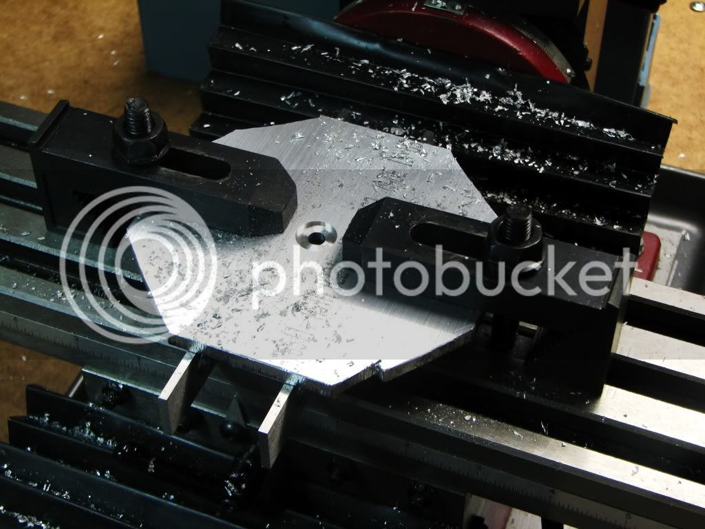
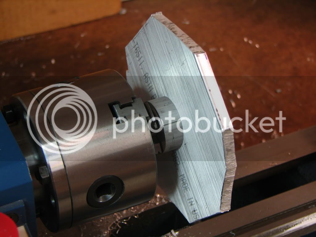
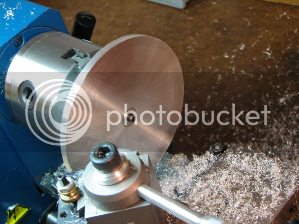
Took a hunk of 1/4 by 5 and chopped off about 4 1/2. Then chopped off the corners. Drilled and reamed the center for 1/4" then milled 1/2" about 1/16 deep. Flipped it and milled another 1/2" round about 1/16 deep.

396d3300.jpg


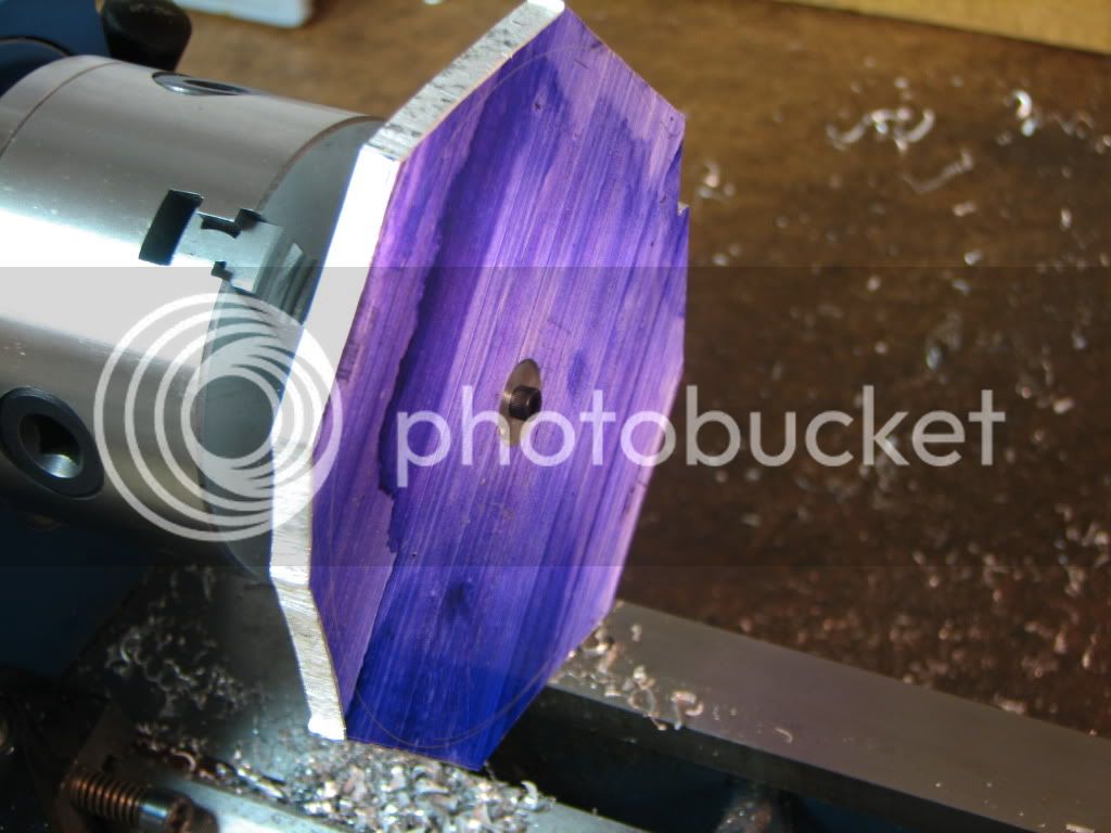
Then I took a 3/8 and turned about 1/8 of it down to 1/4. Tapped it for 6-32. Took a 1 1/4 round (biggest I had), drilled it to 3/8 and faced both sids.
Took a 1/2 round and made a 1/32 washer.
Then mounted the plate.

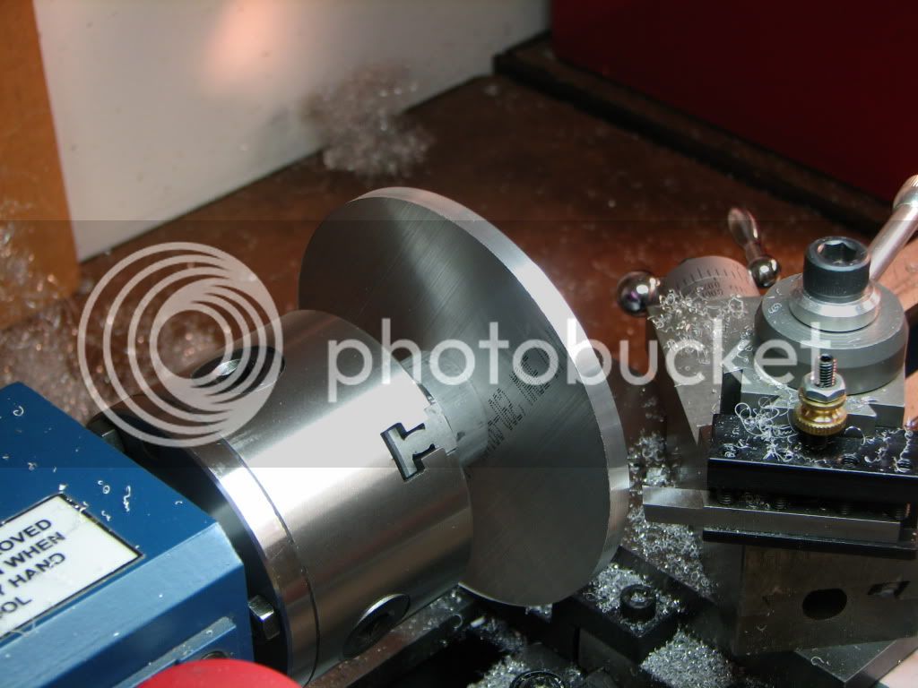
The idea was that the 1 1/4 round would help give some support to the wheel while I turned it instead of placing the wheel straight up against the chuck jaws.

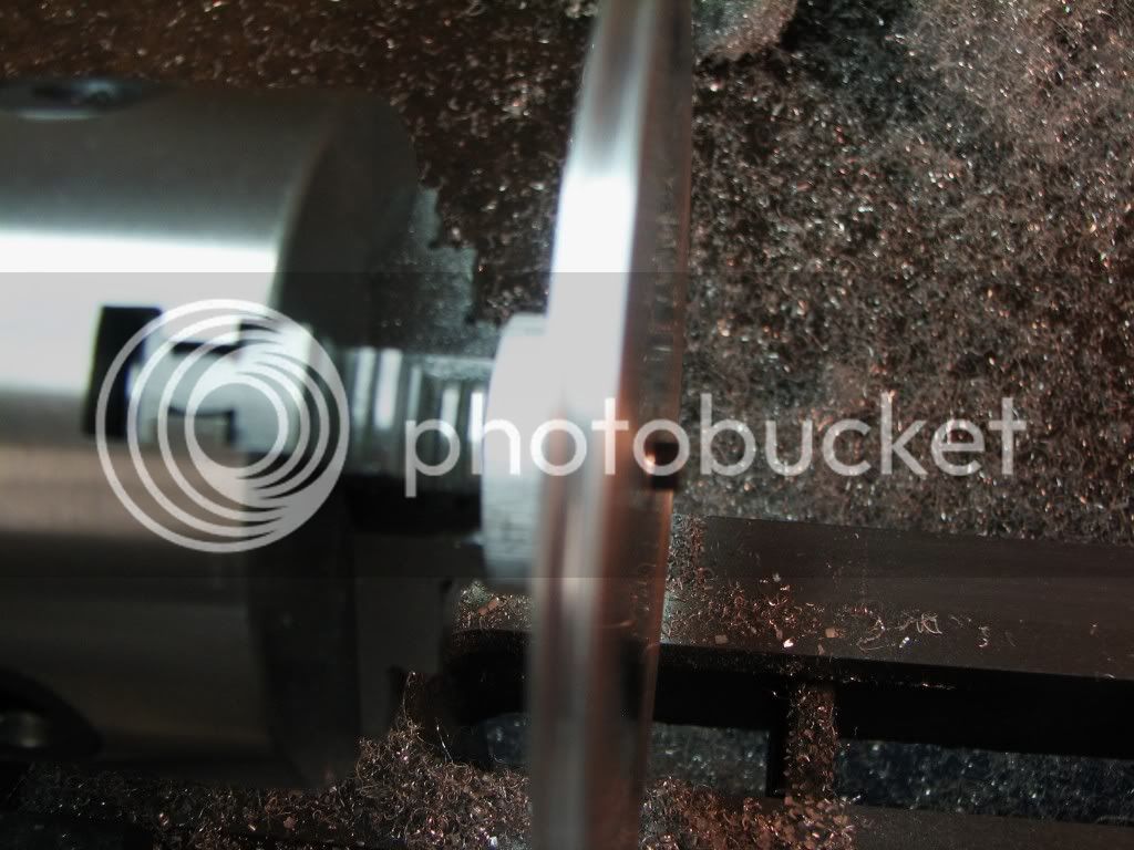
This shot shows the 1/14.

8ff2f0c5.jpg


This shot shows the 6-32 through the washer into the 3/8 round.

efa4e23b.jpg


This shot shows the rim turned down. That went pretty well.

c42b6356.jpg


One side faced. A little difficult. Rang like a bell and had some bad grooving. Playing with speed and feed made it better. Sanding will take care of it.

f9dc5e46.jpg


Here's where things went awry. Unfortunately the pictures came out pretty fuzzy. This next one shows the grove along the rim. It looks good and the sides are even. But in fact, the plate wasn't true and when you look 180 degrees away, the left rim is quite thin.

2fc279f5.jpg


Basically, when I flipped the plate around, it was no longer true. I don't know what I could have done to help. The 1 1/4 collar was supposed to help (and maybe it did). Certainly it would have been better to use a bigger collar and give more support to the plate but that wouldn't have helped keep it true.

Still, I'm pretty happy with the results...I had expected much worse or at least more trouble. The next round (if/when) should be better. But this lets me continue.

It's quite possible my chuck isn't running true and the more distance (radially) the more this would be accentuated. I'm 2 1/4" away from center. The error would be on the order of 0.4 degree not counting whatever the collar contributed. So to some extent I'm not surprised.

One question I would have...
As you know I'm going to drill holes around the center. Would you bling the flywheel first? I'm thinking I can shiny it up on the lathe but having holes around the center would make it difficult. I thought I might bling it first then put some sticky paper on it to protect it...then drill the holes.

Oh...as for the possibility of the wheel wobbling on the axle...I'm not too worried about that. The hub (flange) on either side of it should prevent that. I just needed the 1/4 center to seat it on the axle. It doesn't matter if it's thin. What's important is that the wheel is flat. The question for me is whether a built-up wheel would be better.

Thanks for looking.
 
Thin stuff, sure there is a way other than what I'm thinking. Once the material is rounded I'd switch to a, lord I'm using one and cant think of its name, a backplate? faceplate 6 inch dia and skimmed over for flatness. Slap on one of them sticky sand disk and use the tail stock center to hold the material against the sandpaper while facing the surface(s). Full support should keep the material from flexing.

Bogs post about flywheels, worth the read
http://madmodder.net/index.php?topic=871.msg6640#msg6640


Robert
 
Zee,
I have seen posts where you just put the plate against the chuck and bring a live center up to the plate and friction turn it. Should you need more umph you can use double sided tape.

What I think happened is that the hole had enough clearance for the bolt so it probably had a small amount of run out.

If you go the friction turning way you will want to get closer to a circle on the bandsaw. It will help with the interrupted cut.

Good luck,
Sean
 
As for the bling before drilling, Zee; if you drill then bling, the polishing wheel will tear (maybe not the right word) the metal away from the side of the drill hole that the polishing wheel (sisal/spiral type) goes up against. Hmm....need a better way to describe that. One side of the hole will show a dip in metal thickness in the direction the polish wheel is turning. Anytime you go up against an edge with the polishing wheel that edge will wear unevenly against the wheel compared to the flatter part of the work piece. If you use a harder felt wheel its less likely to have that affect. Experimentation might be in order.

I would polish and drill afterward.
 
Thanks Robert and Sean. The reason I didn't want to use a dead/live center to hold the plate against the chuck (I have used that method before) was that I didn't think I would get the clearance I needed to face the plate. If you look at the 2nd to last picture you can see that the tool post would have collided with the center.

Maybe there was another way...but as it was...I had just enough travel to get the cutter to move from 2.25 down to 0.5. Even then, on my first try I bumped into the screw and had to readjust my cross slide and tool holder.

I should have spent more time verifying that the faced side was true and tried to adjust it. I should also have checked to see if the faces of the chuck jaws were square and even to each other.

Thanks for the link Robert. Very interesting.

Thanks Trout...that's exactly what I was worried about. I'll try polishing first.

The wheel turned out to be a simpler job than I'd thought. If the project goes well then another wheel (maybe even a different type ;D ) is likely.

 
Have had that out of room facing problem, what I did, and it did make me a tad nervous (safety disclaimer) was to take a piece of 3/8 round stock 'bout 3 inches long. put a 60 degree point on one end and center drilled the other. Set that between the stock to be faced and the live center, which in effect moved the live center to the right 3 inches to give me the room needed. Its one of those you hold the nail and Ill swing the hammer, but it worked.

Robert
 
Nifty idea Robert and would make me nervous too.

But what I mean is that in order to cut out at 2.25", I had to turn the tool post and set the cutter on the side closest to me. That means the tool post holder crosses the center axis of the chuck as I move the cutter from the rim to the center.


Hi Zee.

Interesting choice of a project. Us wannabes should learn a thing or 2 here. Thanks again. You have a knack for upping the learning quotient in your posts,

Ron
 
Ah, blame it on the mouse Zeep, he'll never be able to rebut the accusation anyway. :big: You may want to consider the fact that if you bling up the part first and then go back and drill holes in it, you are running the risk of scarring up what you already have polished etc. Perhaps it would be a better idea to do all the machine work and then sit down for a serious fireside polishing session. (ahem) .... you, the piece, some wine, the mrs., the mouse, more wine .... ah yes, a good time. :big: :big:

Too bad about the plate getting skewed when you changed sides :-[ Foozer I think has the right idea about the usage of a faceplate but like so many things in this sport, there are numerous ways of accomplishing the same ends, it's just a matter of what one has available on hand at the time. You're off to a good start at least and I'm sure the finished product will have rewarded us all with entertainment and educational value. Carry on!!

BC1
Jim
 
Seanol said:
Zee,
I have seen posts where you just put the plate against the chuck and bring a live center up to the plate and friction turn it. Should you need more umph you can use double sided tape.

What I think happened is that the hole had enough clearance for the bolt so it probably had a small amount of run out.
Agree-- bolts are not precision locating devices, even with a very close-fit hole. Took me a few to learn that.

 
zeeprogrammer said:
Nifty idea Robert and would make me nervous too.

But what I mean is that in order to cut out at 2.25", I had to turn the tool post and set the cutter on the side closest to me. That means the tool post holder crosses the center axis of the chuck as I move the cutter from the rim to the center.

What type of tool-holder did the lathe originally come with. I use the rocker post when cross slide travel range is at a premium. More than once have I applied the "Fudge!" language when tool travel ran out afore part dimension.

Flywheel V2 coming up?

Robert
 
Thanks Ron. It's good to know it has some value.

Thanks Jim. You've described what should be an excellent time. Careful with the wording there. :big:

I have a faceplate but have never used it. (I was scared but I'm a tad less scared now.)

Here's the spindle...

bba25a1c.jpg


The yarn or thread is inserted into the orifice. It's at the bottom of the spindle and you can't see it.

The wide diameter section is where you insert a little wire to retrieve the yarn that was inserted into the orifice.

The upper (fine) thread will be used to hold the flyer.

The bottom (coarse) thread is used to hold the drive pulley. It looks like I only have 2 or 3 threads so a finer thread would have been better. I can loctite if necessary.

A couple of other changes...

The upper (fine) thread was originally 8-32. But such a die won't clear the 1/8 rod that extends from the thread. So I went with 10-32 and am hoping I don't have to enlarge the flyer. I don't think I will.

For the same reason, the 1/4-20 thread meant I had to reduce the diameter of the rod leading up to it from 13/64 to 11/64. But that still works fine. I had chosen 13/64 for more meat around the orifice but it turns out I have plenty.

Still needs to be blinged but like most of the parts I have to make...that'll be towards the end.

I have difficulty understanding (i.e. seeing and feeling) how the size of a part will turn out...even if the plans are to scale. This model is turning out a bit bigger than I'd thought. But that's okay too.

Just saw your post shred. Thanks.

There wouldn't have to be much error at all to result in some significant error at the rim of the wheel. The rim is 2.25 inches out and I was trying to cut a 2/16 groove out of 3/16...leaving 1/32 for each rim.

The error could be in several places. If the collar wasn't faced true, if the milling I did on the flywheel for space wasn't true, if I had a bit of swarf someplace...that would have been sufficient.

I don't think it was a good way to go. Worth a try...learned some things...and it was fun...but if I repeat this type of flywheel (quiet Marv ;D) then I need a much better method.

Geez...now Robert has posted while I'm writing this. ;D

It's a QCTP. I don't know what a 'rocker post' is. The original holder was that kind that look like square plates with bolts around the perimeter.

We'll see about V2 Flywheel sometime down the road. ;D
 
Rats. I was looking at the picture and realized a major boo-boo. The large diameter section with the hole in it is 5/16 diameter. It's supposed to be 5/16 long too. But it's about an 1/8 too long. Hm...same length as the thread for the drive pulley....hm.

Ah well. Easily fixed without having to redo the entire part.

Could even modify the maiden and leave the spindle as is.
Nah.

The maiden...like all maidens...shall be perfect. ;D

This project has too many opportunities for gutter-talk. I should just move there.
 
zeeprogrammer said:
c42b6356.jpg


One side faced. A little difficult. Rang like a bell and had some bad grooving. Playing with speed and feed made it better. Sanding will take care of it.

I like the idea of turning the compound slide, so as to reach and machine the side of the disk.

That should make for a more rigid setup, then traversing the compound from the front.

Nice project choice, and nice work on your parts so far.
 
zeeprogrammer said:
It's a QCTP. I don't know what a 'rocker post' is.

Don't want to HJ your thread, Rocker or lantern post, same same. In the mock up photos the faceplate is 6 inches in diameter. using the lantern toolpost is the only way i can skim the surface. To do your flywheel which is about as large a diameter that this lathe could manage using a tailstock center would require some shifting of the cross slide, hence the reduction of working area. It may say 6 inch but some times 4 inch is more than she can handle.

Ya I know

Robert

DCP02127.JPG


DCP02128.JPG
 
Back
Top