A little backpedaling and I'll show how the valve was made. The main cylinder rotates on cast iron bushings turning on a 1/4" polished steel shaft. The air enters one side of the standard, connects with a passage in the shaft, travels through the shaft to the valve port in the shaft. As the main cylinder block and bushing rotates, a radial hole (one of five) passes over the port and transfers air to the appropriate cylinder to drive the piston. In the second half of rotation, the cylinder port passes over the exhaust port on the shaft and air is exhausted through the shaft and out the other side of the standard.
This is similar to the porting that Ken used in his Six Shooter elbow engine (last months award winner) except that I am using a much smaller diameter shaft and needed a different method of forming the two air passages through the shaft from the standard to the port and a slightly different method of making the port.
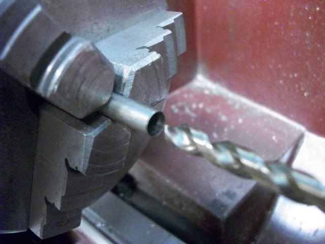
The first step is to drill a hole in the end of the shaft. The hole is 7/32" diameter, 1.25" deep was first center drilled and then drilled to full diameter without intermediate sizes. Super high precision is not needed for this hole.
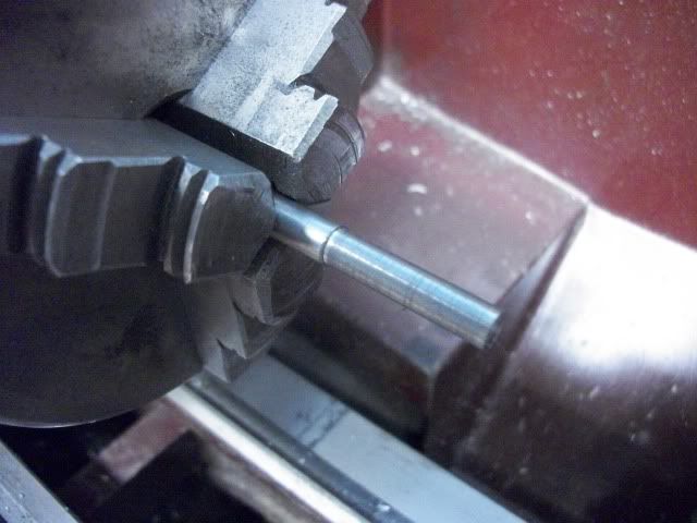
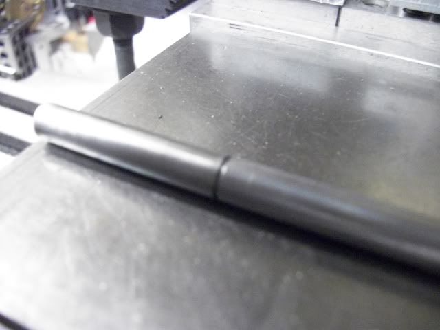
The shaft is then extended from the chuck and parted off at a length of 1.5". The shaft is then extended from the chuck for a length of about 2" and turned to 7/32" or to fit hole drilled in the first part.
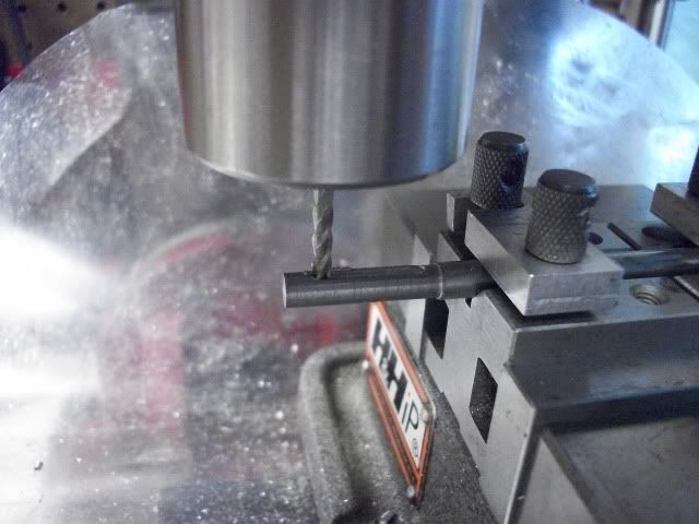
This fit should be close but should not an interference fit. When the thin shell of the first part is fitted over the turned down section of the second part, I don't want it distorted. It will be secured and sealed with locktite but before it is fitted, the air passages must be milled. Out of the lathe and into a V-block in the mill vise.
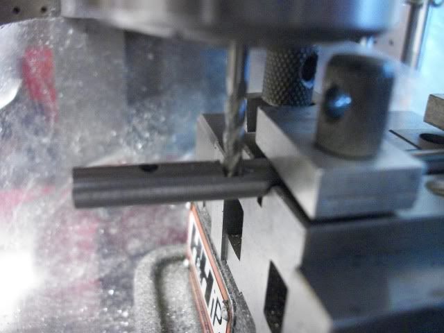
Two 1/8" wide slots are milled on opposite sides of the shaft. The length of the slots is not critical but it should not extend to the end of the shaft or to the shoulder. The depth of each slot is .062" leaving a web thickness of .126".
After the slots are milled, and the edges cleaned up with a file, the locktite is applied to the shaft and then inserted into the shell being careful not to allow sealant into the slots. The shaft is not removed from the V-block during this process so that the position of the slots is retained.
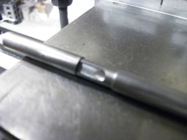
After the locktite has cured overnight, one hole is drilled through the outer shell to intersect the groove. This hole will match up with the air passage in the standard to allow air into the slot. The port is positioned, according to the dimensions of the standard and the position of the passages in the cylinder block. At this position, the port is mill as a transverse slot to the same depth as the lengthwise slot.
The depth of this slot affects the timing of the valve and was worked out using experimentation with an Alibre' solid model. It may not be optimal and may not even work. Actual experimentation will be needed for that answer. If the cross slot is milled too deep, it may weaken the shaft and also may bleed between pressure and exhaust. Too shallow and there may not be enough power.
The same process is carried out on the opposite side of the shaft for exhaust.
I hope this makes sense and is of interest.
Jerry