Swinging Elbows

Home Model Engine Machinist Forum

Help Support Home Model Engine Machinist Forum:

This site may earn a commission from merchant affiliate links, including eBay, Amazon, and others.

Captain Jerry

Project of the Month Winner!!!
Project of the Month Winner
Joined
Dec 2, 2008
Messages
971
Reaction score
8
Open for discussion

I'm not ready to build this yet but I think it is possible. I just thought I would put it up here for discussion.

Jerry

Basevariable.jpg


View attachment variable elbows.pdf
 

As the angle between the two cylinders approaches zero, there is little or no rotational force. It might work down to 20 degrees or so.
Interesting concept at any rate.
 
Captain,
Firstly four cylinders will not work (OK maybe it was just for illustrative purposes) at 90° A'la elbow engine.

With 4 cylinders at 90° elbow engine style at the 90° rotation you reach a point of singularity - the cylinders simply tow each other out and lock. (Try it with one piston pair in place or look at my vid on this and you will see what I'm getting at.)

[ame=http://www.youtube.com/watch?v=eqdyO4FcFS4]http://www.youtube.com/watch?v=eqdyO4FcFS4[/ame]

Ignore my voiceover comment about 5 cylinders I was mistaken - but 4 won't work (at 90°)

At the increaced angle it should be O.K. down to about 110° and at 180° (in line) there is no stroke.
So I'm guessing you want to be able to swing it from 180° (zero stroke = won't run) to 90° (stroke = pitch circle diameter of cylinders) then you need 3 or 5 cylinders.

Frictionally a 6 cylinder is rather like two threes working together - from this it follows that cylinder numbers should be "prime" 3, 5, 7 etc.

Obviously you need some sort of joint at the elbows and the cylinders need to accomodate the changes in stroke occasioned by the change in angle.

Interesting exercise just thinking it through.

I've sent you a PM on my build notes.

Ken
 
Ken

So far, it is just a thought exercise. If it ever gets built, it will be used to test some ideas and options that are often talked about but never proven or tested and maybe some ideas that haven't been talked about yet. This frame idea will not be able to test all ideas but it should be able to answer the question of the range of possible angles between 90° and 180° and in the process give some answers about flexible joints.

Your engine clearly proved the axial valve and seals can eliminate the oil spray. The rigidity provided by the center bracket will be more obvious with time. I predict that time and use will allow the seals to seat without undue cylinder wear.

I think this design will use the axial valve but will not use seals or bearings. I expect that it will leak a little air and oil, but not as much as the face valve of the original design.

It will not be reversible. The complication of additional air passages would cloud the issues and reversing is well understood.

I think it will use cast iron for the pistons and have ball joints at the flex point but could also use half/lap or knife/fork joints.

The cylinders will be either aluminum or cast iron turning on a polished steel center shaft. If the cylinders are aluminum they will have cast iron or bronze bushings.

I don't think there is any doubt that jointed elbows will work. There is a wide range of opinion on the range of angle. My bet is that it can be made to run well past 160° after break in.

If there are any other ideas that need testing, please speak up. There is plenty of time. This isn't going to happen tomorrow.

Jerry
 
This seems like a small change but could be important. By putting the pivot in line with the cylinder where the piston is at TDC, it keeps the piston/head clearance constant. When the pivot is centered as in the previous model, the piston/head clearance increases as the stroke decreases ... a bad thing!

Jerry

Capturecornerpivotelbows.jpg


Capturecornerpivotelbowsclosed.jpg
 
Captain,
See attached *.pdf - I found that swinging on the corner is lousy for geometery - but swinging on the intersect of the inboard cylinders works well and keeps the dead length constant.

However that won't permit any form of stiffener (other than an adjustable one perhaps).

Swinging on the centreline intersect would permit some sort of hinged stiffener - but the redundant volume in the base of the cylinders increaces with swing - lousy for efficiency with steam or compressed air (wouldn't matter for hydraulic).

2c
Ken

View attachment ELBSWING Model (1).pdf
 
Ken

I see you have been through this thought process before. What else did you discover?

I think I like the pivot on the inboard cylinder intersect. That is what I was trying to say but used too many
words. I guess I will just have to rely on the wonders of modern pharmacology for the stiffener.

Jerry
 
Captain,
You gotta love them little blue pills. Knew a guy who took too many - then needed a whole tube of Deep Heat for his arm.

If you put the pivot point any closer inboard than the cylinder intersects, the reverse happens - the pistons descend further into the cylinders exacerbating the dead length problem - so I guess the cylinder intersect it is. (I mistakenly thought you were going to pivot at the corner edge of the cylinder - which will keep that constant - no good purpose in that - that I can see.)

Captain Jerry said:
I think I like the pivot on the inboard cylinder intersect. That is what I was trying to say but used too many
words.
No you explained it just right - I'm the idiot who didn't read it properly.

As regards the stiffener - I removed mine from my elbow engine and it still turns over by hand and runs - pretty much the same as with it.
It sounds a little more "grumbly" so the reaction forces are probably springing the 90° slightly and my "springy elbow thingies" are taking care of it but at the expense of some increaced side load on the pistons.

That said your "hinged elbow thingies" should take any of that kind of deflection in their stride.

What else have I found - Hmmm - you keep sparking me so keep the ideas flowing.

Regards,
Ken

PS - in my build notes - my comments on the number of cylinders and friction etc are on page 20-21 - to save you wading through all the guff.


^^^^ VIDEO ^^^^

I think I have the geometry worked out, at least good enough for Alibre'. The number of cylinders is just for the convenience of comparing piston positions at 180° apart. I know I could do that with a six cylinder design but I think I am leaning towards a five cylinder design.

Alibre' has no problem with rotating 4 cylinders, but strangely enough, it can't handle just two cylinders very well. And there is no friction in Alibre' so it is a purely geometric issue. It will rotate through almost 180° before locking. I think I have an answer but I want to investigate before I say something stupid.

Here is a screen capture of the thing working. The articulation and the rotation are manually controlled so I can't do them simultaneously.

Jerry
 
Captain,
Not many people chipping in to this thread - I think you've scared them off.

Further to my comment about your elbows taking flex in their stride - I was wrong - the flex will be at 90° to your hinges - but since the flex will be very little I would presume a little play in the "hinges" would take care of it.
Alternately your suggestion earlier of a spherical joint - but that approach will almost certainly have limited articulation.

Ken
 
I'm here. If you search deep enough on earlier posts, you will see that I've being wondering about flexible elbows on these engines for a while. Swinging elbow idea is new to me but I'll follow along. ;D
 

With the swinging geometry, You also get a variable volume / compression ratio effect.
An opportunity? or just another worm in the can? You decide. Maybe the reason for the silence
is guys like me scratching their head with both hands and nothing left to type with.

Regards,
Maverick
 
Ken

I'm not ready to build this yet but I can still think about it. I am still leaning towards a spherical joint for two reasons.

1. I have worked out a method that is extremely simple to make and they have about 270° of articulation. An example
of this joint is shown on my three cylinder opposed wobble plate engine shown here. These joints are articulating
40° but that is nowhere near the maximum available.

[ame]http://youtu.be/YR7SH5YDQGY[/ame]

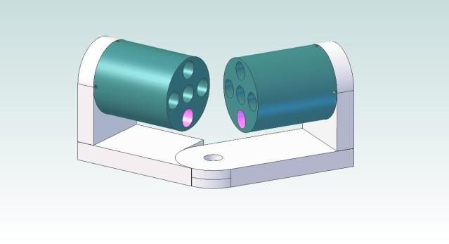
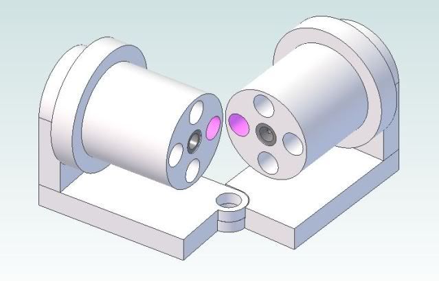
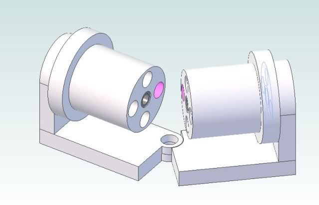
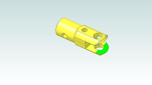
2. Half lap joints like I showed in my 3D model are easy to draw but very difficult to machine with the same accuracy and
the cantilevered pin can add a point of binding.

Knife and for joints are better balanced for thrust forces than lap joints and would be my second choice. The most important point for the joint is that it must have very little slop. To be able to change the relative angle, it must be able to articulate, but any slop will lead to alignment problems and binding.


Noitoen

I'm glad you are watching and still interested. Yes, there has been plenty of discussion of flexible elbows but as I see it, there is a difference between "flexible", (think RUBBER TUBE), and articulating, (think hinged). A fully flexible elbow could allow the two pistons to be forced out of the same plane, which screws up the geometry of this engine. If the joint only articulates, the two pistons must remain in the same plane and the two cylinders must also remain in the same plane. This is the single most important constraint in the geometry of this engine. Ken's center axis joiner assures the coplanar arrangement of the cylinders on his engine and even though he has said that it didn't change things much when he took it off, I think it was important in establishing the coplanar relationship.

Maverick

Variable volume/displacement is an important part of this design. As the engine articulates from the 90° orientation to 180°, the displacement changes from a maximum value ( depends on the bore and the PCD of the cylinder arrangement), to ZERO. If the "swinging elbow engine" can be built accurately, and is running freely at 90°, it should accelerate as the angle is increased up to some angle as the displacement is reduced. If there were absolutely no friction, it would continue to increase in speed dramatically, approaching infinity as the angle approaches 180°.

But of course friction does exist and as the displacement is reduced, so is the power and somewhere along the path, friction will begin to slow the speed and the engine will run out of power but the point where that happens is very dependent on the materials used and tolerances maintained. There have been several estimates as to what the maximum angle is that can be achieved. That could be seen by some as a challenge.

The more I think about this thing, the more anxious I am to build it. I may not have the skill or the equipment to do it justice but It is worth the time to try.

 
I'm here also....got my eye on you two ! ;D

Dave
 
Captain,
Another problem with the "hinge" elbow - at 180° (in line) they could rotate to any position and then be unable to bend.

O.K. I know that doesn't make a lot of sense - bear with me - as you approach 180° the propensity for the two pistons to rotate increaces - thowing the alignment of the hinge out of whack - as it bends it will realign itself - but at some point it will introduce self-locking forces. Perhaps the motor will fail to run because of overall frictional limits before this particular limit is approached - but I thought I would give it a mention.

Regards,
Ken
 
Noitoen, I am aware of that - but at 180° if you were to rotate it by hand the elbow hinges would would be free to rotate out of synch making it impossible to change the angle without first lining them all up by hand first.
Similarly as you approach 180° (I know the engine is going to come to a halt somewhere as you approach 180° as the stroke diminishes to zero) there will be a tendency for the elbows to try and rotate the hinges out of synch which will eventually reach a self locking condition - what I don't know is whether or not this will be the limiting condition.

If as Jerry thinks, the engine will run to about 160° it probably won't be.

Ken
 
Ken

I think that while the pistons would be free to rotate in the bore, at 180° there is no force that encourages that. The pistons then rotate WITH the cylinder. When the cylinder has rotated 90°, the hinge pins are locked in relation to the base hinge. This is another of those questions that will only be answered by building it.

Jerry
 
This is the joint that I think will work best for this experiment. It provides plenty of articulation in the XY plane as shown here. This is a video.


With a very slight modification, it will also allow about 15° of articulation in the YZ plane as well. Rotation of the ball member has no effect on the articulation in any plane. Rotation of the clamp member is where the problem would occur, and that only becomes evident when leaving the 180° orientation. I believe that with the slight modification, the clamp member will re-align with the XY plane. I can not model this because Alibre' has no means to limit motion based on interference between faces. It will have to be tested.

This is the modification:

RodClamp.jpg


While thinking about this, has anyone got any theories as to what happens when the engine is articulated beyond 180°?

Jerry

 
Captain Jerry said:
at 180° there is no force that encourages that.

Agreed - but at 179° there is - the question is will the "self righting" of the elbows defeat the "self locking" tendency.

However your suggested design renders this moot - even if it does move out of whack it has sufficient articulation to reenter the self righting zone.

Captain Jerry said:
While thinking about this, has anyone got any theories as to what happens when the engine is articulated beyond 180°?

I would guess it will pick up where it left off - restarting again at (whatever)°

Ken
 
Back
Top