- Joined
- Dec 2, 2008
- Messages
- 971
- Reaction score
- 8
Dang it! I can't stop thinking about this silly project. I'm thinking about doing it like this.
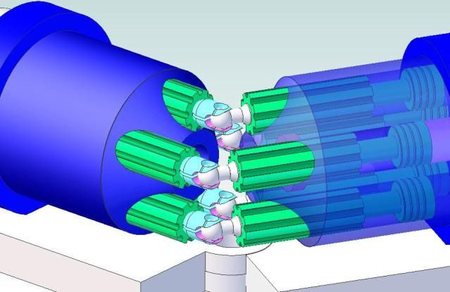
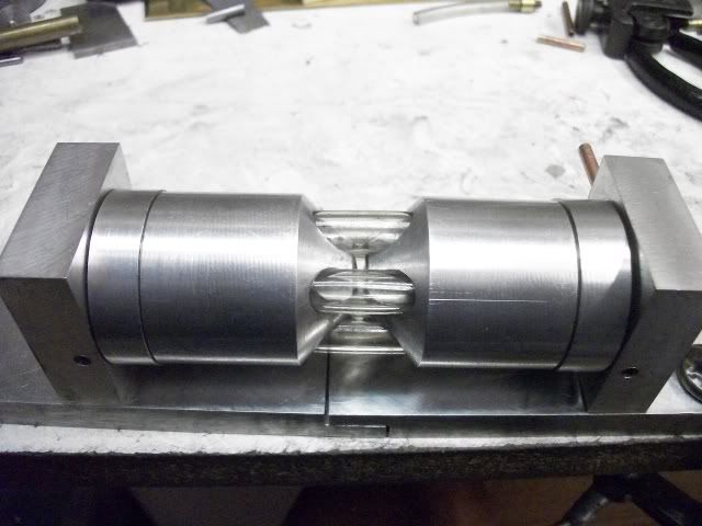
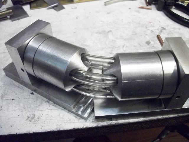
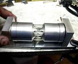
The way I am thinking is that friction is the big problem with this engine so I am looking at ways to reduce it. One way to do that is to reduce surface contact. I am looking at the piston as having two separate functions ... piston and crosshead. The piston of course must be full diameter to seal the bore. The crosshead does not need to seal the bore but must provide constant linear contact. To reduce surface contact, the crosshead portion can be fluted as shown. The area between the piston and the crosshead is reduced to eliminate surface contact in that area and the piston has three oil control groves. It could be made to include an o-ring if necessary. The cylinder is aluminum and the piston/crosshead is cast iron.
Don't be shy. Tell me what you think. There is still plenty of time do do it differently.
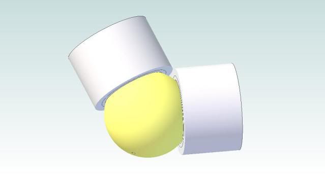
I have also discovered an additional problem that can occur if the cylinders are allowed to reach the 180° position. At that position, the pistons can shift longitudinally in the bore. At that point, the hinge point is locked in the bore and cannot be expected to re-align or recover. A limit will have to be placed on the swing angle.
Thanks for watching
Jerry
The way I am thinking is that friction is the big problem with this engine so I am looking at ways to reduce it. One way to do that is to reduce surface contact. I am looking at the piston as having two separate functions ... piston and crosshead. The piston of course must be full diameter to seal the bore. The crosshead does not need to seal the bore but must provide constant linear contact. To reduce surface contact, the crosshead portion can be fluted as shown. The area between the piston and the crosshead is reduced to eliminate surface contact in that area and the piston has three oil control groves. It could be made to include an o-ring if necessary. The cylinder is aluminum and the piston/crosshead is cast iron.
Don't be shy. Tell me what you think. There is still plenty of time do do it differently.
I have also discovered an additional problem that can occur if the cylinders are allowed to reach the 180° position. At that position, the pistons can shift longitudinally in the bore. At that point, the hinge point is locked in the bore and cannot be expected to re-align or recover. A limit will have to be placed on the swing angle.
Thanks for watching
Jerry
 ;D
;D