Stephenson's Rocket--Working Model

Home Model Engine Machinist Forum

Help Support Home Model Engine Machinist Forum:

This site may earn a commission from merchant affiliate links, including eBay, Amazon, and others.
This morning I Loctited the boiler rings in place. This isn't really a big deal on three of the rings. The fourth ring may be a challenge. It is split around the engine mounts, and split again on the bottom half below the motor mounts to clear the pivot support bar. If the Loctite doesn't want to hold on this ring I may have to "pin" the individual ring sections in place with 0.039" diameter pins inserted thru the ring sections and into corresponding drilled holes in the boiler body. I wanted to paint the boiler today, but may have to put that off until tomorrow depending on how rapidly the Loctite sets up.
 
While I was walking today---I was thinking about stay rods. The smallest size socket head capscrew I carry is a #4, which has a 0.182" diameter head. If I spent a little time making up rod ends from 1/16" mild steel, then I can silver solder them to the ends of the stay rods. I think this is the best solution I have came up with yet, and since the stay rods will be painted black, I think it will work quite well, and give a good solid attachment between the stay rods and the rest of the machine.
LJn3Jm.jpg
 
I think my bolted stay-rods are going to work out just great. They are (I think) the last parts to be fabricated, painted, and assembled before I start earning my living as a wheelright.
5ynvvy.jpg
 
The driver is the fellow I put into all my production machine layouts for custom built machinery. Customers always want to see an operator shown at the correct scale. He is five foot nine inches tall and weighs 160 pounds. He is "North American Standard size." I didn't design him. Another engineer did, and I stole him from a set of engineering files years ago. My software package has the ability to scale him larger or smaller, but all the work I have ever done for customers is always done to "full scale". I had to calculate the scale I wanted to make my Stephenson's Rocket to and then scale Elvis to the correct size. He looks to be too small in relationship to the Rocket, but if you look at any You-tube videos of the rocket, the operators shoulders are about even with the top of the boiler. My cylinders are larger than "real scale" because this engine is going to run on air. Without the extra power gained from the "change of state from steam into liquid vapour" I was afraid that the cylinders running on air might not be strong enough, so I oversized them by about 30%.
bgpMjg.jpg
 
Brian, in the back of my head I kept questioning just how that simulated lagging on the boiler would look. ill have to say it looks really nice. good job.
 
Werowance--I've never done that before, but I am very happy with the results.
I am a firm believer in welding fixtures. I find it impossible to hold things at a specific angle and rotation and expect them to stay in place while being silver soldered. This shows firstly, a two part welding fixture for attaching the stay rod to one of it's foot plates. The jig has to be two part so it can be disassembled to remove the part after it is silver soldered. The second fixture is a simple one piece jig for welding the second foot plate in place. There will be clean up after the welding is finished, and final shaping on the footplates to make them match the drawing.
mVrvZ1.jpg

7PKMc2.jpg

ShfdiH.jpg
 
Slowly I'm getting closer to the end of the end. The short stay rods are finished, fitted, and painted. The only outstanding things to build now are the two stay rods that stabilize the tall smoke-stack. Then I will reassemble everything and get started on the wheels. I tried to buy material for the outer rim of the drive-wheels on Friday afternoon, but the man at the metal suppliers was way behind schedule, having been shut down on Wednesday for Canada Day. He told me he would check it out Monday and let me know if they have any extremely heavy wall tube. This is kind of a sucky picture, but black doesn't photograph terribly well.
0CdoH8.jpg
 
Today all of the painted pieces were reassembled, with thankfully no major "gores" in the paint. That always seems to be an issue for me. The longest stay rods that help steady the smoke stack will be done tomorrow. Then I will jump head and shoulders into the wheelright business. Each drive wheel will be built up from 15 individual pieces, which include 12 spokes, a two piece inner hub, and a rim.---And yes Sparky, I will be using my tig welder for that.
igoQ1C.jpg

wnPUfk.jpg

bnS034.jpg

9cbxUi.jpg
 
TA-DA!!!--The last two stay rods are painted and installed. I'm just waiting for a call back from my metal supplier to confirm that he has the material I need for the outer rim of the two big drive wheels.
qFlK8p.jpg
 
TA-DA!!!--The last two stay rods are painted and installed. I'm just waiting for a call back from my metal supplier to confirm that he has the material I need for the outer rim of the two big drive wheels.
qFlK8p.jpg
Good job 👍. Is your chimney stack top staying as is or are you going to fabricate a castellated end as orig. Just wondering how to go about making something like that.
 
I thought about making a castellated top like the ones you see in Youtube videos of the Stephenson's, but I don't have the resources to make one from sheet metal. Somebody even offered to3D print one. I think I'm just going to leave it as it is.
 
Today I turned seventy four. Ringo Star and I share a birthday, but he is six years older than me. Happy birthday Ringo!! I spent the entire day setting up the engines to run in the newly painted chassis. One engine started up right away with no drama. The other engine was a stubborn pig all day, and I still don't have it running. I did pick up the material for the large drive wheels today, and I'm looking forward to starting on them as soon as I get the second engine to run.
 
Thanks Ron---
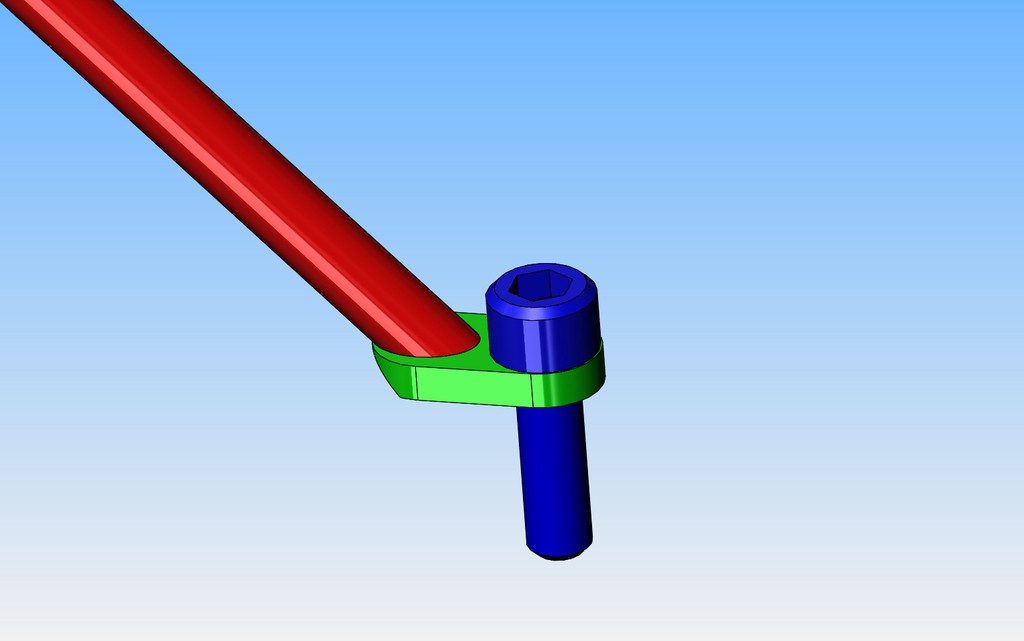
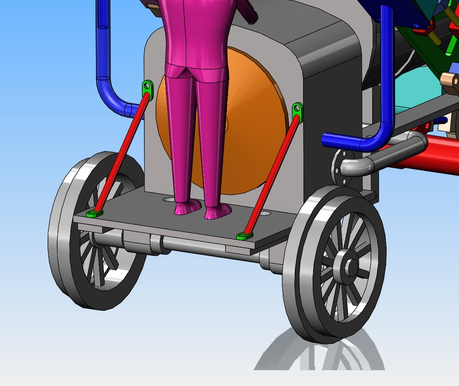
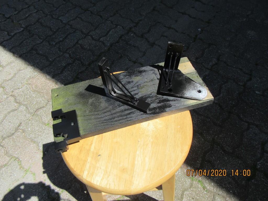
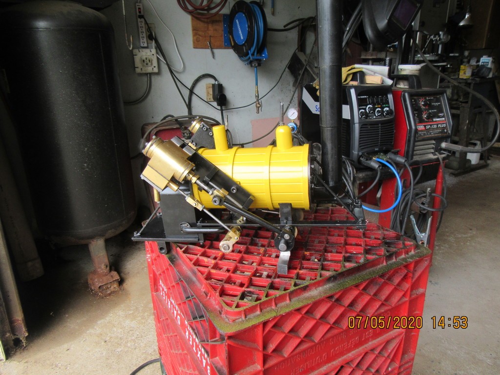
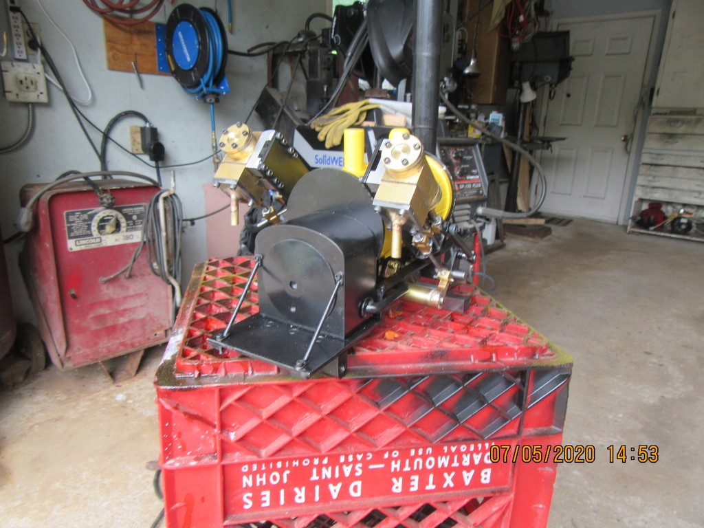
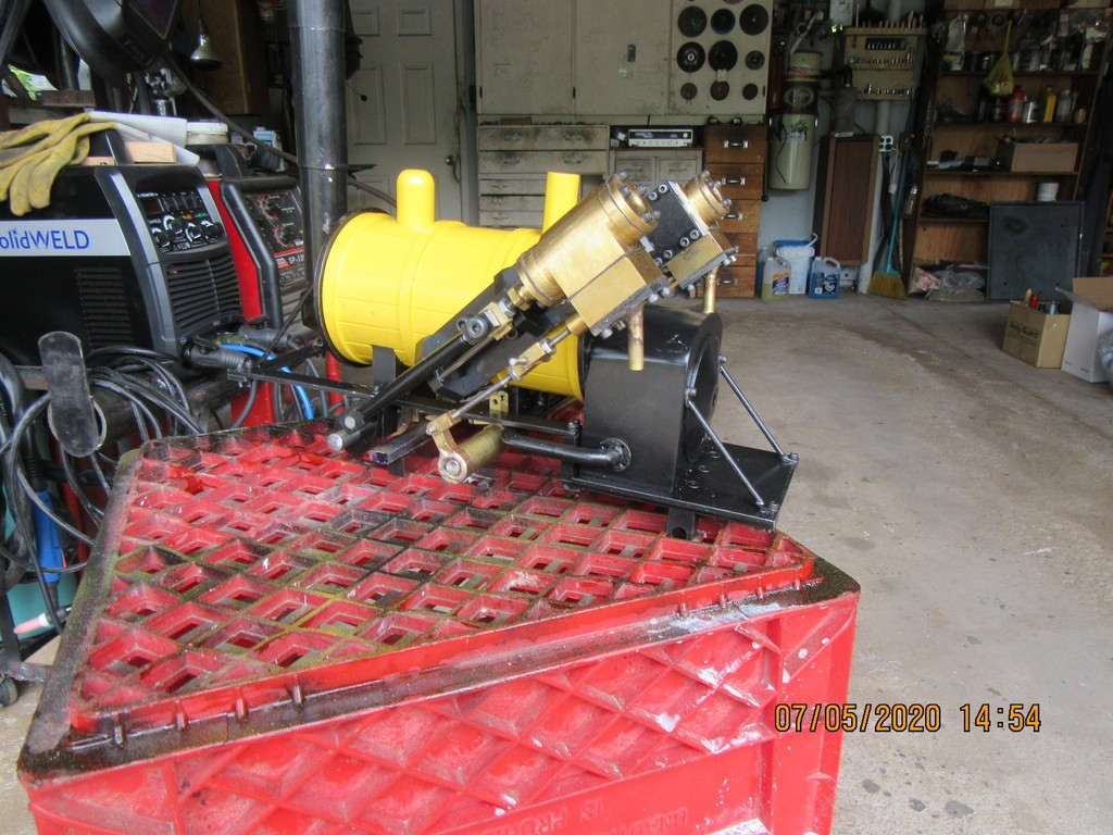
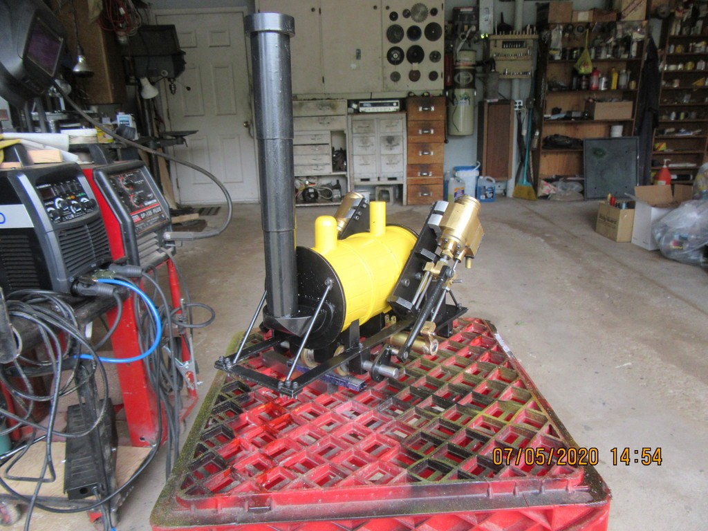
So, here we are kids!!! After what seemed to be an awful lot of frigging around, both engines are up and running on the model. To time these slide valve engines properly, the cylinder has to be either at full extend or full retract, and the valve control rod must be exactly at mid travel. That is not really as easy as it sounds.--A hint--put 3 setscrews at 120 degrees apart in each eccentric hub. Although that is not good practice on most hubs, if you don't do it, then when the engine is timed perfectly, the single set screw will be hidden behind something and you won't be able to access it. The engines are "lurching" a bit, but that is just a matter of timing, and can be corrected.
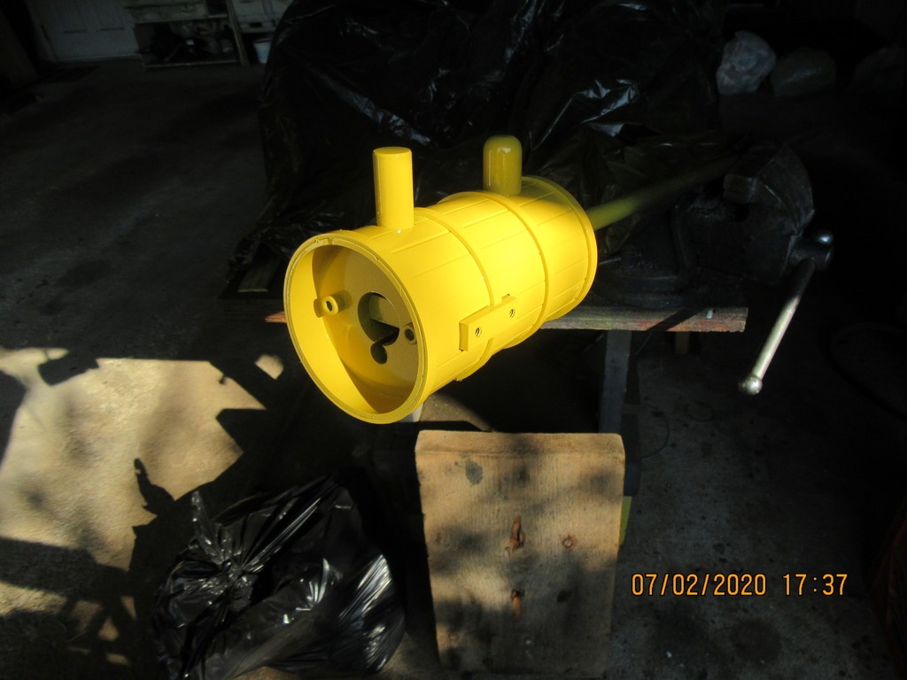
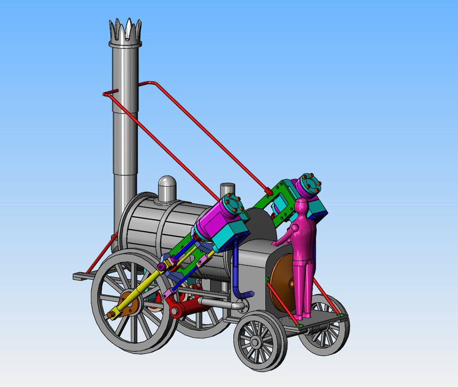
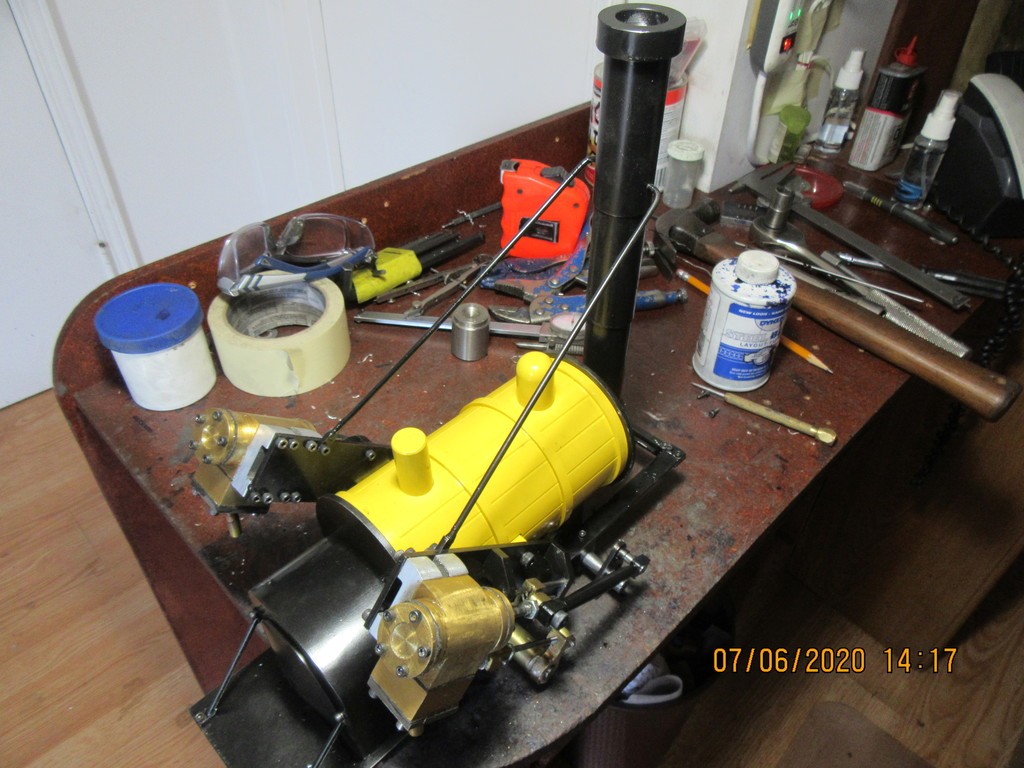
 

Latest posts

Back
Top