Rod's Aussie Shed

Home Model Engine Machinist Forum

Help Support Home Model Engine Machinist Forum:

This site may earn a commission from merchant affiliate links, including eBay, Amazon, and others.
Oh, I forgot to say, my order from Little Machine Shop in the US arrived last night. I was very impressed with their service and would not hesitate to use them again. Shipped within 24 hours and arrived in 10 days. Main things I wanted were imperial 5C collets to go with my metric set and some transfer screws. I really only wanted their metric transfer screws but ended up buying one of very size they had in stock. The only thing left on my wish list is a linisher attachment for my bench grinder and a set of ball end mills. Oh and a sine bar and a set of sine blocks and .....

So after I digest some car repairs and finally sort out my shed and finish a few projects, DRO's will be on the agenda.
 
Well, a few things went right today. I cleaned up the lathe and put it back together and touched up most of the missing paint. Everything is working fine. I finished off my accessory power and am happy with the result. All tested and working!


The DRO socket is just wishful thinking for now but it is getting a lot closer now give or take a busted diff or two. I have not included a switch for it and it is live all the time if the powerpoint is turned on. I borrowed the wiring idea from Hare and Forbes as one of their lathes with coolant built in just had a lead hanging down with a computer IEC socket for the pump so I followed their lead.

The plumbing side of the project needs some revision. The pump came with a length of pipe and an agricultural looking tap. I tried to use them as it had a nice mount but it hits the crossslide when it is right across so I will ditch the supplied nozzle and run with a magnetic base coolant nozzle.


I went down to tradetools today and bought one of these tool boxes for $68

EP-213_3.jpg


With the lid removed, the height is identical to a drawer unit I intend to use.

I have found from some sketches I have done up that using prebuilt cabinets for a lathe stand sets the dimensions of your stand and I still need to allow for a coolant drain (which might be able to go down between the drawer units).

The other thing is to get enough clearance under the cabinets for the coolant pump and still having the lathe at a good work height. My solution for this is to use a roller drawer unit and one of these. Being a bit shorter, this unit will see the stand length to be just right and the coolant tank and the tool box together will be the same as the depth of the roller drawer unit so I have come up with the building blocks that are just right for me.

So anyway, I butchered this brand new toolbox by removing the lid and all of the catches as soon as I got home.

The other thing I have to sort out is the coolant drain. I had a friend who is plumber around today and he did not think the punches they use for pressing out sink plug holes would handle the thickness of the drip tray so I am back to plan B, making a tail that is held on by countersunk brass screws. I think I should also see if I can make up a flanging tool to flare the hole a bit so the coolant drips off the tray.


So the UFO's Unfinished Objects) floating round my shed are.
1. Electrical wiring to compressor and a couple of other power points while we are at it.
2. Drill motor power feed
3. Arduino controlled Rotary table controller (Hopefully Programmable, maybe with an SD card).
4. Make some collet racks for drawers
5. Make Late QCTP tool holder rack.
6. Lathe stand so my machine never falls over again!
7. Replace the busted drawer unit and see if the other drawers can be incorporated into lathe stand.
8. pour a level slab once I can wheel the lathe out

So much to do and not enough time!

By the time I tick them off, I might be able to afford some DRO's and then I will be have some time to think about an engine to get Baz off my back! ;)
 
Hey Rod, good to see things are coming together and no damage to the lathe. You've given me lots of ideas for my little shed and lathe! I too live in Brissy and own the same lathe, I've just got it all adjusted and running sweet.

I built a lathe bench and installed some shelves and draws from bunnings. There is no reason other than cost stopping me adding more drawers under the existing ones. I like these deeper draws as I can fit chucks, rests tool holders etc in them.

Dave.

mylathe.jpg
 
Is that a granite/resin slab on your bench Dave? If so, where and how much mate?

cheers, Ian
 
Hey Rod, good to see things are coming together and no damage to the lathe. You've given me lots of ideas for my little shed and lathe! I too live in Brissy and own the same lathe, I've just got it all adjusted and running sweet.

I built a lathe bench and installed some shelves and draws from bunnings. There is no reason other than cost stopping me adding more drawers under the existing ones. I like these deeper draws as I can fit chucks, rests tool holders etc in them.

Dave.

Dave thanks for the photo, glad you are getting ideas. It seems you made the right decision to build your own stand in the light of my lessons! I am on the south side (too close to Hare and Forbes!). If you want to catch up and see things first hand, send me a PM.

... now you've given me more ideas. It just so happens I have two legs similar to your Bunnings ones. I had forgotten I had them. I wonder if I can use to hold my bench? They are surplus because I bought two shelves and joined them together so only needed one leg in the middle. The shelves were rated to hold 450 kg each so they are definitely strong enough, but they may be too high at 910mm.

How high is the top of your bench?
 
Hi Ian, I wish mate! No it's not granite, it's a laminated chipboard kitchen bench top from IKEA. I found them to be the cheapest supplier of 50mm tops. I believe a 2.6m length was $80. This material should stay dimensionally stable if it remains dry - to ensure this I coated all seams and the bottom with a couple of coats of varnish. It's supported underneath by two 150x50 steel rails (you can't see these in the pic). So hopefully this bench will stay rigid, flat and true.

Rod, personally I wouldn't use those legs for a lathe stand. Just too flimsy I think. There is an eBay seller based in loganholme that sells cheap 2nds quality steel. I used them to buy the reinforcing posts, I reckon you could weld up a custom bench pretty cheaply that would be much sturdier and custom designed. You could then cut those legs down to size and use them to mount drawers however. The drawer kit from bunnings is only $50 and is a massive 900mm wide x 200 tall x 600 deep.

I believe my bench top is about 850 high at the bench top. My concrete slab has about 50mm of runoff so I added levelling feet to the bench legs making one side 50mm higher than the other. You're welcome to come take a look if it will help.

Hope this helps.

Dave.
 
Dave, thanks, yes I have discounted using the legs now. They would need to have been shortened and therefore not worth the effort. It looks like you have a non standard Drip tray. Is that right? The standard tray hangs below where the legs mount up so I have to allow for that too as the cross braces I was planning on putting in to hold the lathe at its mounting points will need to be a bit higher than the bearers. That's probably a good thing as it means it won't need a bench top. Sounds like your shed floor is like mine.

I usually get my steel at Supersteel at Coopers Plains which is on the way home or Metalcorp at Oxley which is not much out of the way. Metalcorp are a tad cheaper and will sell half a length. Last time I made up a bolt on bracket for the bull bar so I can now carry a full 8 metre length on the roof.
 
Sounds good. Yep I had to modify my drip tray to sit flat on the bench. Basically I just took to it with the angle grinder to cut down the lip that sits bellow the tray bed.
 
So many projects and not enough time.

First shot of my lathe stand


Do you like it?

And another one of my drill powered Mill power feed


well, the variable speed reversing motor controller anyway!

And my Rotary table controller complete with SD card storage


And the menu system slowly taking shape in the evenings

[ame="http://www.youtube.com/watch?v=pFAD4D4-VJM"]http://www.youtube.com/watch?v=pFAD4D4-VJM[/ame]

Anyway, this weekend, the focus is on the lathe stand. I hope to have it mostly together tomorrow.
 
You going pole vaulting Rod ;D

Yes all 8 metres of it. Looks like we drive different types of cars on different sides of the country too!

The stand will use about 6 m of the 35x35mm SHS and it will marry to 65x35 RHS top rails. I bough the drawer unit this afternoon but not stuff for the bottom shelf. I thnk it will be pretty quick to put the frame together.
 
Excellent,

looking forward too seeing the new stand,

My lathe has the same stand at the one yours is on. Have been using it over the past couple of days, I keep thinking about the picture of your machine laying down and having a rest, gives me goosebumps thinking of having 850 kg laying on top of me.
(or my 10 yo son, he uses it too with me supervising of course)

Might go down the same avenue with the bench some time.

The car, I bought it in 2003. was 6 months old, my pride and joy, just sold the wifes Hilux, regretting it now
 
Excellent,

looking forward too seeing the new stand,

My lathe has the same stand at the one yours is on. Have been using it over the past couple of days, I keep thinking about the picture of your machine laying down and having a rest, gives me goosebumps thinking of having 850 kg laying on top of me.

Maybe just bolt it down. This video which is of one like my lathe seems to indicate you will get a better finish on machined surfaces if you do. He has just built a clamp to hold it. This would have been an option if I had a level floor.

[ame="http://www.youtube.com/watch?v=Uk2Q9H4RLp8"]http://www.youtube.com/watch?v=Uk2Q9H4RLp8[/ame]

I gotta remember this when I am finished.
 
Excellent,

looking forward too seeing the new stand,

Well, I have not got much to show for a full days work.

First off, my bandsaw was cutting poorly and by the time I got it cutting straight, I could have had my stand half cut out.


Anyway, I learnt a bit more about aligning this awesome tool. The main culprit on crooked cuts is the alignment of the blade at the driven (motor) end. If the blade is on an angle the cut will be crooked as the blade will wander away from the perpendicular. It is good to start by removing the blade and replacing it with a 30 mm ruler held in place by tightening up the guide wheel eccentrics but this time I needed to tweak it afterwards and check how it was cutting until I thought it was sweet!

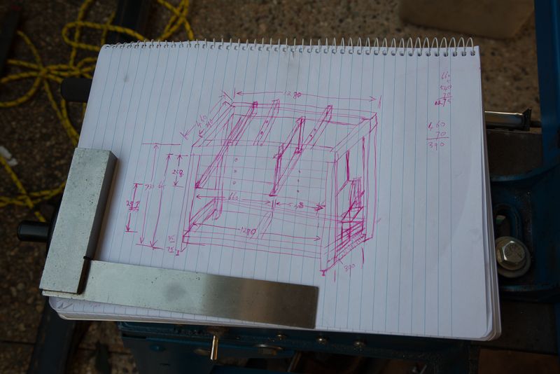
And then I consulted my highly detailed CAD drawings


Some of you might wonder how I can cut down an 8 metre length of steel in my 3.8 metre long shed. Well, the answer is, I can't! I roll the bandsaw down to the other end of the house and set up in the carport.


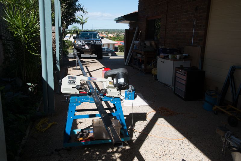
Yup, that's why I like to keep my tools on wheels if I can!

This time I had to open the gate for the first cut which was a pain. Whilst members in the northern hemisphere are thawing out after winter, we are heading into ours and the wind was coming straight through the open gate AND the band saw was not cutting straight so I was punished for an hour or so!

I also decided to check out the positioning of all of the accessories


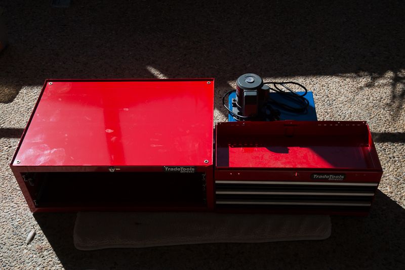
The coolant system will actually sit lower than the cabinets but the motor sticks up in the road so I decided to modify a toolbox to use as drawers so I still had a bit more storage AND room for the coolant system. Also, using a second drawer unit would have seen the stand as being about 1450mm long nd I just don't have room for that! So this configuration matches the length of my Hafco AL320G lathe very closely. :)

So after a day of cutting stuff down, I ended up with this by about 3:00pm:


The black stuff is 65mm x 35 mm RHS and the blue stuff is 35m x 35mm SHS.
Would you believe I paid good money for the rusty Crap which is 75x50x6mm angle iron

So from the top down we have:

short Black - top cross members (some will be supporting the lathe itself).
short Blue - Bottom Cross members
medium length blue - legs
Long Blue - Bottom front and back rails
Long Black - Top front and back rails
Rusty Crap - Angle Iron for removable wheels
4 x 32mm x 3mm flats - to be used as end caps for top rails to make it look tidy.

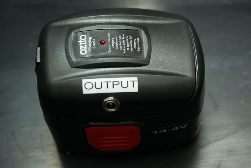
Castors - Well I have three sets of these complete with fasteners shown in the small plastic bag. They came with my grey Tactic drawers in the shed. They are pretty crappy but the wheels will be for occasional use and while they are not what you would buy for this application, they were free with heaps of spares, so I decided that they have to be good for 80-100 kg each which is all I need. (I gotta move the 165 kg Seig SX3 out of the doorway before I can wheel the lathe out anyway!

I decided not to use angle iron to support the drawers as it meant the stand had to grow in length so I am going to use 5mm x 50mm flat steel as "Hangers" and let the drawers sit on an inverted T suspended from above. The purpose of the small black blocks is to mount these hangers to.

So with that explanation, the 50mm x 5 mm flats sitting on top are hangers and the tops of the inverted T's. The short black RHS sections are mounting brackets for the hangers. The short piece of 50x5mm steel is the same length as the depth of the toolbox so it will hang down from above on the outboard edge.

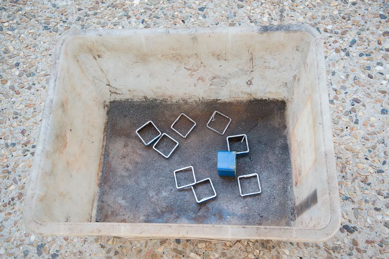
So that leaves us with 4 small, sort of square pieces (32mm x 35mm x 8mm) which you can see below the three black RHS brackets.

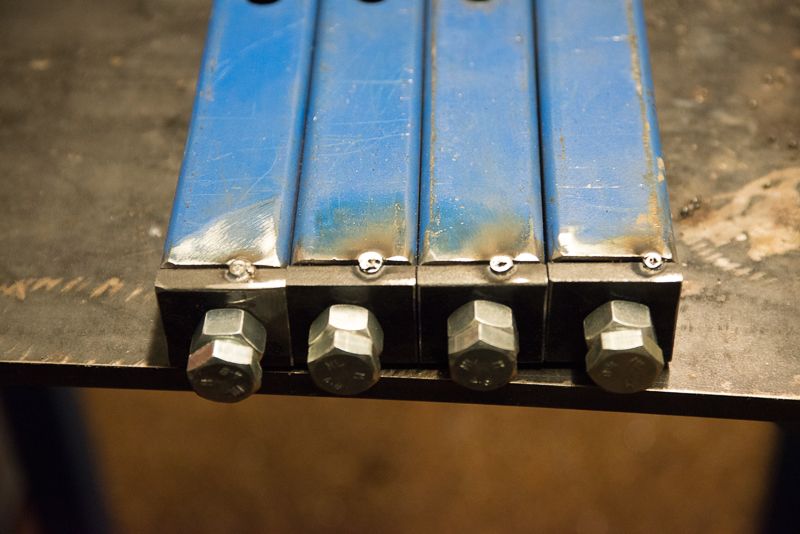
Well these are to be attached to the bottom of the legs to hold the adjustable feet so I took them back into the shed. 8mm steel, might be a bit thin for a M12 thread but I remember reading somewhere you only need three threads to hold stuff and it equates to 4.6 threads. I had some 10mm steel I could have used but the 8mm x 32mm flat is a good match for the 35x35 SHS and even includes a welding fillet!

Anyway, I took the legs and these bottom pieces back to the shed and after a while, I came had the feet all sorted and tacked into position.


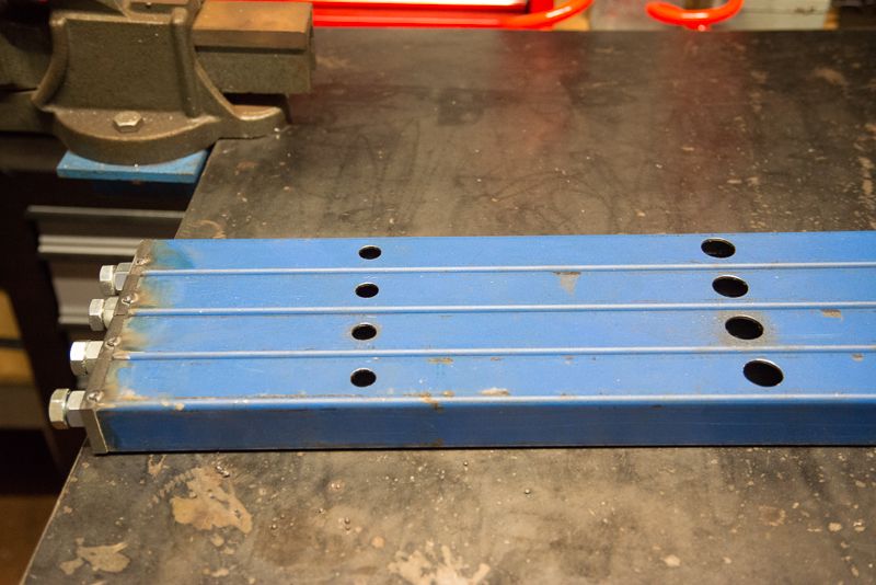
and some holes drilled in the legs to mount the removable wheels


I was expecting to run out of welding gas during this project but I really expected to be able to do more than three spot welds! I really did not hav ethe tie to go and top up with gas during the week so tomorrow I will focus on mounting the castors to the rusty angle iron and turn up a few pins for the removable castors.

I will say that when I first reviewed the example shown earlier in this thread I wanted to mount the wheels so they did not overhang the lathe stand. However, once you get into it, you need to make sure that teh caster hace clerance from the frame an din my case, this worked out to be 130mm. I also considered other mounting systems but then realised that I had to make decisions abut how this was going to work and after half an hour of puxzzling, decided the easiest design was to follow what was shown so I drilled two holes through each leg, The top hole is 19mm diameter and the bottom hole is 13mm to suit a 12mm bolt or pin.

I will turn up a set of 19mm dia pins which have a 10 or 12 mm hole through them to attach the wheels assemblies. I also had a 22 mm drill but decided that was a bit too big a hole to drill through 35mm SHS and keep the strength I want.

So far, all good! I was very fussy (unlike me) with getting dimensions right and It will be few days before I weld it up but I still h ave a fair bit to keepeme busy tomorrow turning up pins and mounting up the castors. If I get time, I would like to duck down to the new Jaycar electronics store at Browns Plains to get a few bits for other projects I have on the go!
 
Hi Rod,
Believe I bought same Reversibe DC motor speed controller though device has yet to arrive from "Qkits.com.
Please post when you get mill table feed up and going.

I am in no hurry to bush engineer my mill table feed. For now just looking for new ideas and options.No harm with "Monkey See---
Monkey Do" to get best option.Getting sick and tire of cranking when milling long jobs.

Gus, Don't wait for me I am afraid. I have lots of stuff happening. Anyway on the mill power feed front, nothing much has happened. I still don't really know how to mount the cog that will drive the clutch. The cog is a press fit on a 12mm shaft and had a needle bearing in it. I have some 12mm steel so I figred I would start with one or two bearings and work it out from there.

I did one small power feed related thing yesterday and decided a power pack might be handy so I modified the charger to include power output. Note the charger plug pack plugs into the left end of the top plate.


I've got two of these batteries which came with the unused donor drill. I am not sure if I will use them for the power feed or not, but for a $ or so and a quick soldering job, it looked like it could be a handy thing to have in a workshop.

Yesterday, I did not do any more on my lathe stand but did get a replacement drawer unit installed after the lathe fall destroyed one precious drawer. I also came up with a good idea wich cost me $12 for a cheap spanner which I hacked into two and threw the open ended piece away.


Then I tapped the hole I had drilled in my QCTP mounting bolt as it was sized for an M10 thread and turned up a washer from some 1 1/8" round stock.


And now I have handle to loosen the QCTP so I can chamfer things easily.


Anyway, a bit of a spur of the moment idea that was inspired by watching some youtube videos of someone who had a nice handle that let him change angles so easilly which was something I tended to avoid because I was using a big shifter that was not much fun to use. The handles miss each too which is great bonus!


So there you go. a quick 10 minute original "Rod" project which I had not seen elsewhere before!

Hi Rod.
Now dreaming(or mentally designing) a compact Power Feeder like the ones from Taiwan. Bought one for the BridgePort Mill 20 years ago.Worked so well. Now scrounging for a cordless drill to cannibalise motor. Will need some bevel gears. Just bought some gear cutters.Project will take some time. Just like Rod ,I have to many on the plate.Ha Ha ha:wall::wall::wall:

Gus, if you can cut gears, somebody suggested to ditch the motor gearbox and go with a worm drive so the motor runs along the end of the table driving a worm that turns a cog to drive the leadscrew. That makes for a very compact layout. Apparently you can buy the bare motor cheap on eBay.
 

Latest posts

Back
Top